
Single-phase optical current transformer
a single-phase, optical current transformer technology, applied in the direction of magnetic measurements, measurement using dc-ac conversion, instruments, etc., can solve the problems of large weight, difficult to manufacture in a smaller size, and complicated fabrication process, so as to reduce the influence of temperature variation on the measurement accuracy attributable to the length of the first and the second optical paths, and reduce the length of the first and second optical paths. , the effect of reducing the influence of temperature variation
Patent Information
- Authority / Receiving Office
- US · United States
- Patent Type
- Patents(United States)
- Current Assignee / Owner
- Publication Date
- 2015-01-13
Smart Images
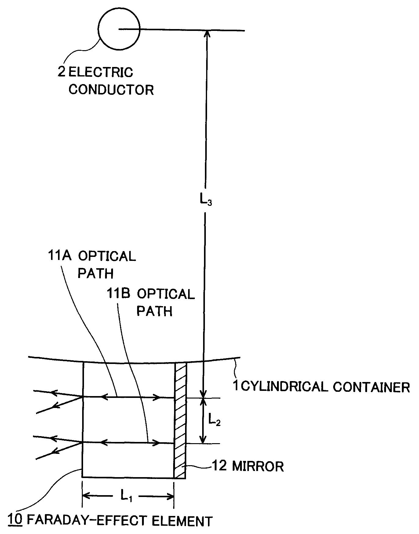
Figure 1 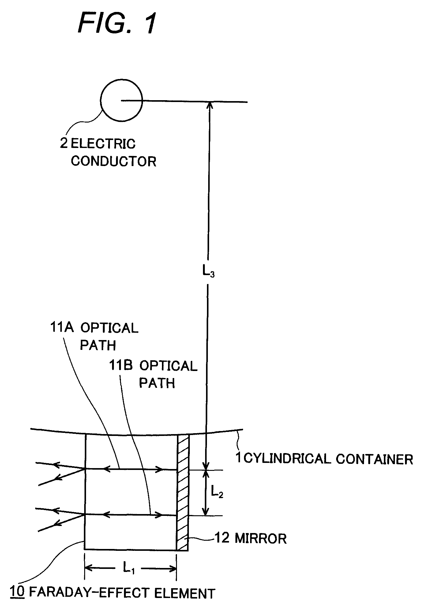
Figure 2 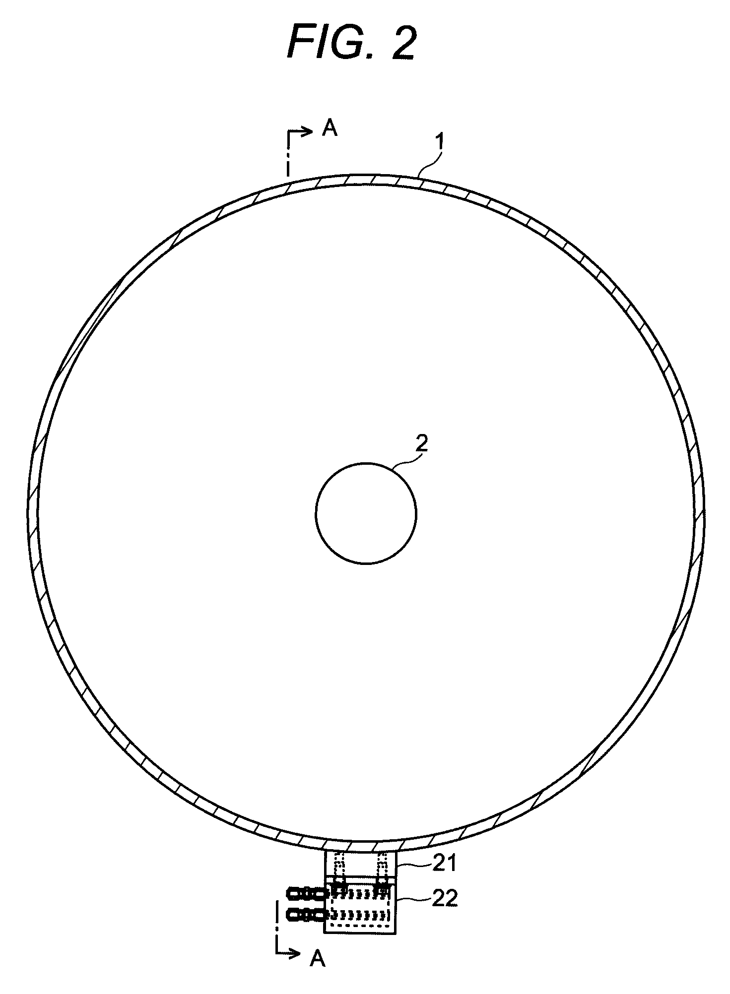
Figure 3
Abstract
Description
TECHNICAL FIELD
[0001] The present invention relates to a single-phase optical current transformer particularly to such a single-phase optical current transformer as is capable of measuring reliably single-phase large currents.BACKGROUND ART
[0002] To measure current flowing through an electric conductor of high-voltage in a gas insulated switch gear (hereinafter referred to as GIS) or similar apparatus, a wound-type current transformer has been conventionally used. The transformer of such type is a through-type current transformer comprised of an endless core and a secondary winding through which the electric conductor passes. However, the wound-type current transformer is large in size and heavy in weight. Because of this, consideration has been made about application of an optical current transformer that uses the Faraday effect, which is a rotation phenomenon of polarization plane of a light due to an effection of magnetic field. Such optical current transformer is suitable particul...
Examples
embodiment 1
[0036]Details of the single-phase optical current transformer by the present invention will be explained referring to FIGS. 2 to 5 that illustrate an example of an application to GIS or gas insulated buses. The cylindrical container 1, inside which the electric conductor 2 is accommodated, maintains electrical insulation by insulation gas filled therein.
[0037]An installation base 21 is secured on the part of the outer peripheral surface of the cylindrical container 1 with welding, or with other suitable method, namely on the undersurface of the cylindrical container 1 with less subject to direct sunlight in this example as illustrated in FIG. 2 and FIG. 3. The manner of attaching is such that, when viewed in the cross-sectional direction, the seat of the installation base 21 is intersect with the axial direction of the electric conductor 2 through which current flows. A case 22 in which the Faraday-effect element 10 is to be stored is detachably secured on the seat of the installati...