
Implantable electrode lead
a technology of electrode lead and electrode elongation, which is applied in the direction of internal electrodes, transvascular endocardial electrodes, therapy, etc., can solve the problems that patients with cardiac pacemakers the electric lead thereof can heat up in nuclear, and the patient's cardiac pacemaker typically cannot be examined in nuclear resonance tomographs. only to a limited exten
Patent Information
- Authority / Receiving Office
- US · United States
- Patent Type
- Patents(United States)
- Current Assignee / Owner
- Publication Date
- 2015-01-27
- Estimated Expiration
- Not applicable · inactive patent
Smart Images
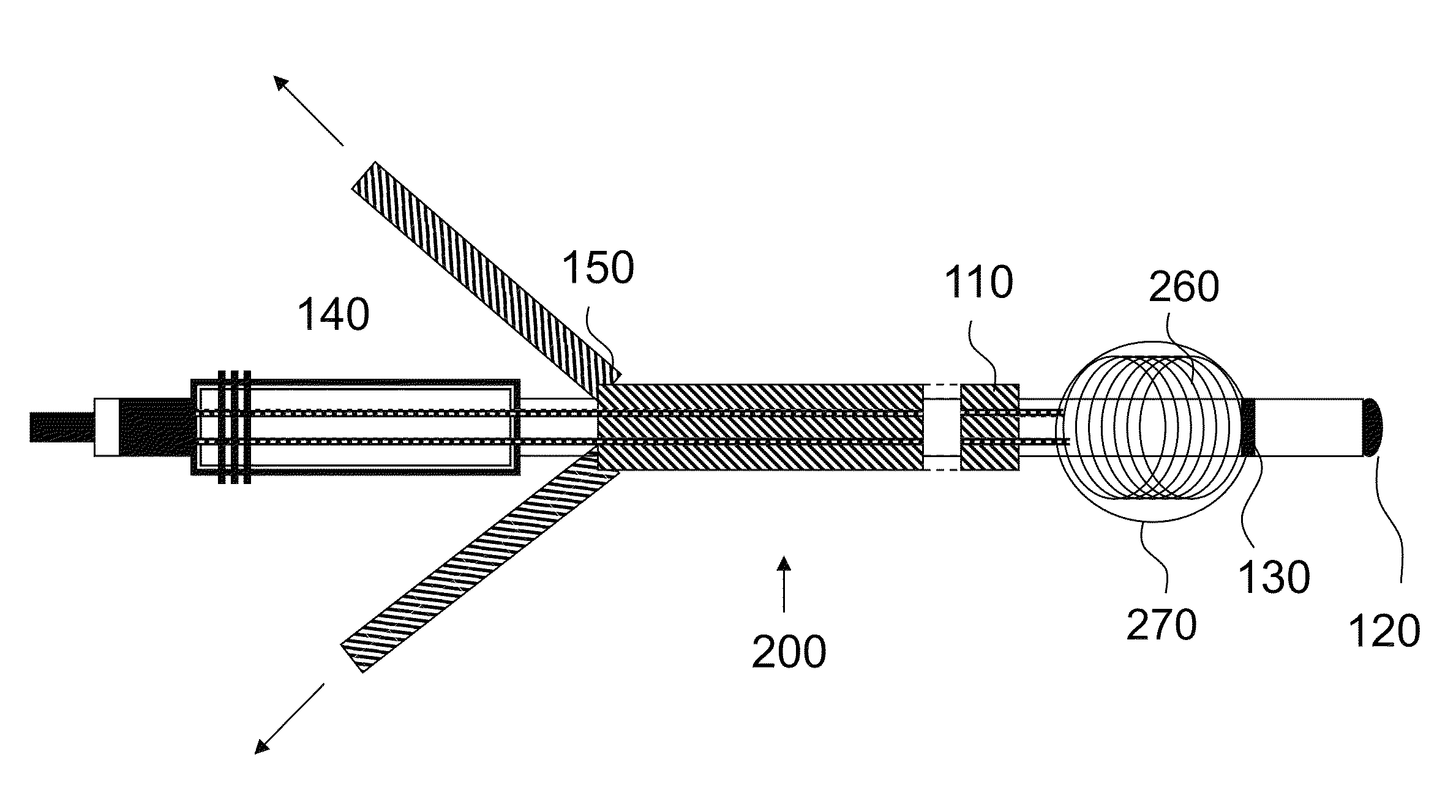
Figure 1 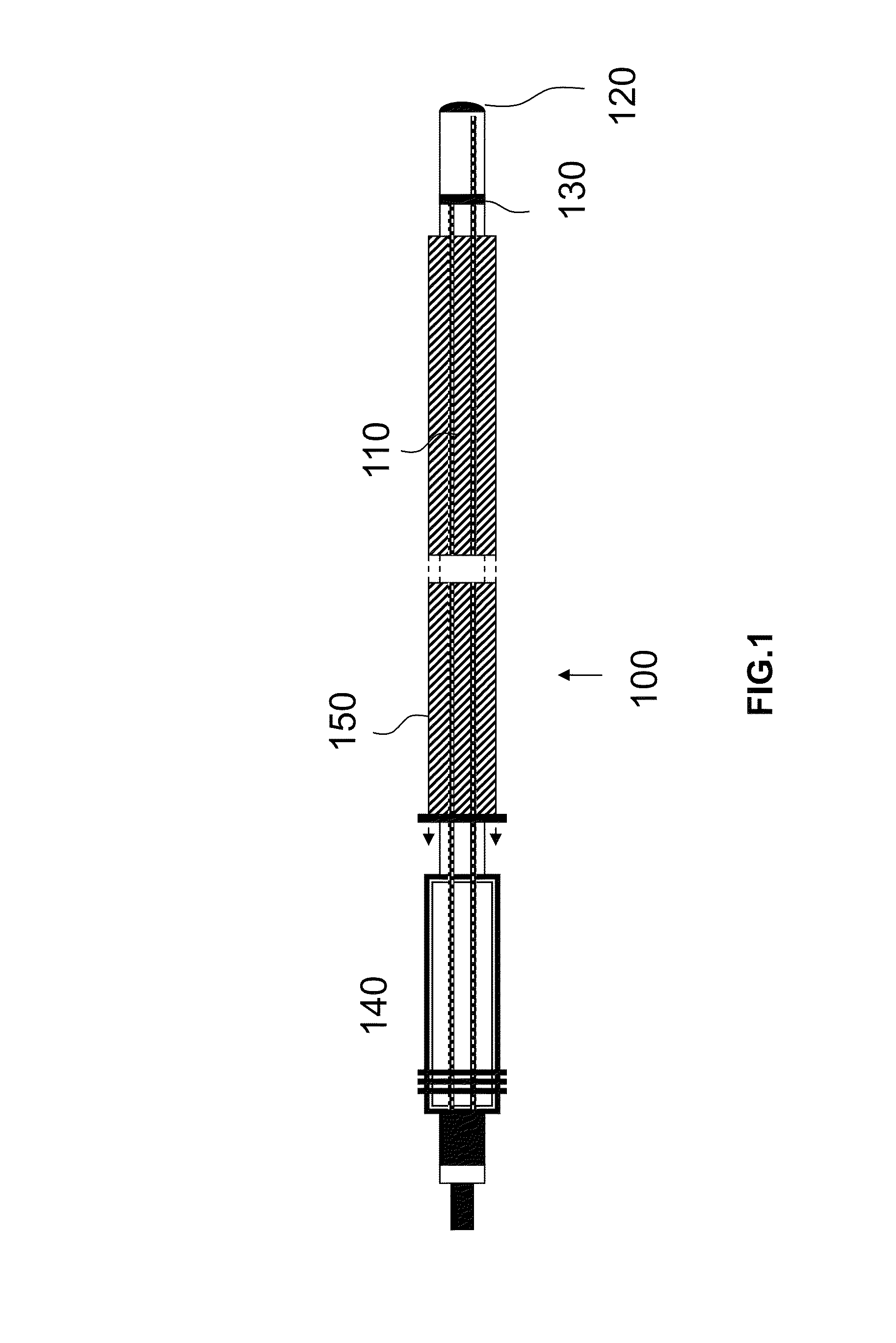
Figure 2 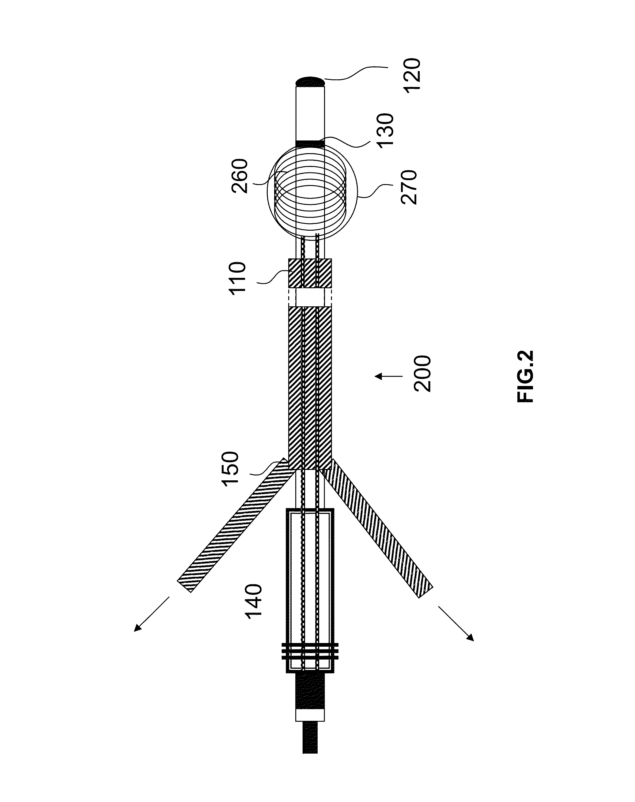
Figure 3
Abstract
Description
[0001] This application claims the benefit of U.S. Provisional Patent Application 61 / 568,182 filed on 8 Dec. 2011, the specification of which is hereby incorporated herein by reference.BACKGROUND OF THE INVENTION
[0002] 1. Field of the Invention
[0003] At least one embodiment of the invention relates to an implantable elongated electrode lead.
[0004] 2. Description of the Related Art
[0005] Electrode leads of are connected, for example, to implantable cardiac stimulators such as cardiac pacemakers, cardioverters, defibrillators or the like, and may also serve as mapping catheters for diagnosis or neurostimulation.
[0006] Such electrode leads have the disadvantage that the electric lead thereof can heat up in a nuclear resonance tomograph because the alternating magnetic fields in the nuclear resonance tomograph induce notable electric currents in the electric conductor. For this reason, patients with cardiac pacemakers typically cannot be examined in a nuclear resonance tomograph, or only to a...
Examples
Embodiment Construction
[0031]FIG. 1 shows an electrode lead 100 according to the invention, before implantation. The electrode lead 100 comprises an insulated supply lead 110 or jacket, a bipolar electrode pole (tip: 120, ring 130) and a corresponding connector or connecting plug 140 and an insertion aid 150 to be used temporarily, in order to create an elongated shape upon implantation. In the example shown, this insertion aid 150 is designed as an introducer sheath or tube over the electrode lead. Alternatively, however, a rigid stylet or a mandrel can be used.
[0032]In FIG. 2, the electrode lead is shown upon completion of the implantation. In addition to the features stated in FIG. 1, a deformable supply lead section 260 of the electrode lead is now shown. In this embodiment, the deformable supply lead section forms a coil in the distal region of the electrode lead having a diameter of 3-15 mm. The altered shape of the deformable supply lead section 260 is induced either by way of a preformation of a j...