
MEMS gyroscopes with reduced errors
a gyroscope and error reduction technology, applied in the field of gyroscope structure and circuitry, can solve the problems of limiting the useable capping pressure, limiting the noise that can be achieved as reasonable yield, and limiting the manufacture cost of such gyroscopes. the effect of driving coriolis
Patent Information
- Authority / Receiving Office
- US · United States
- Patent Type
- Patents(United States)
- Current Assignee / Owner
- Publication Date
- 2015-12-15
Smart Images
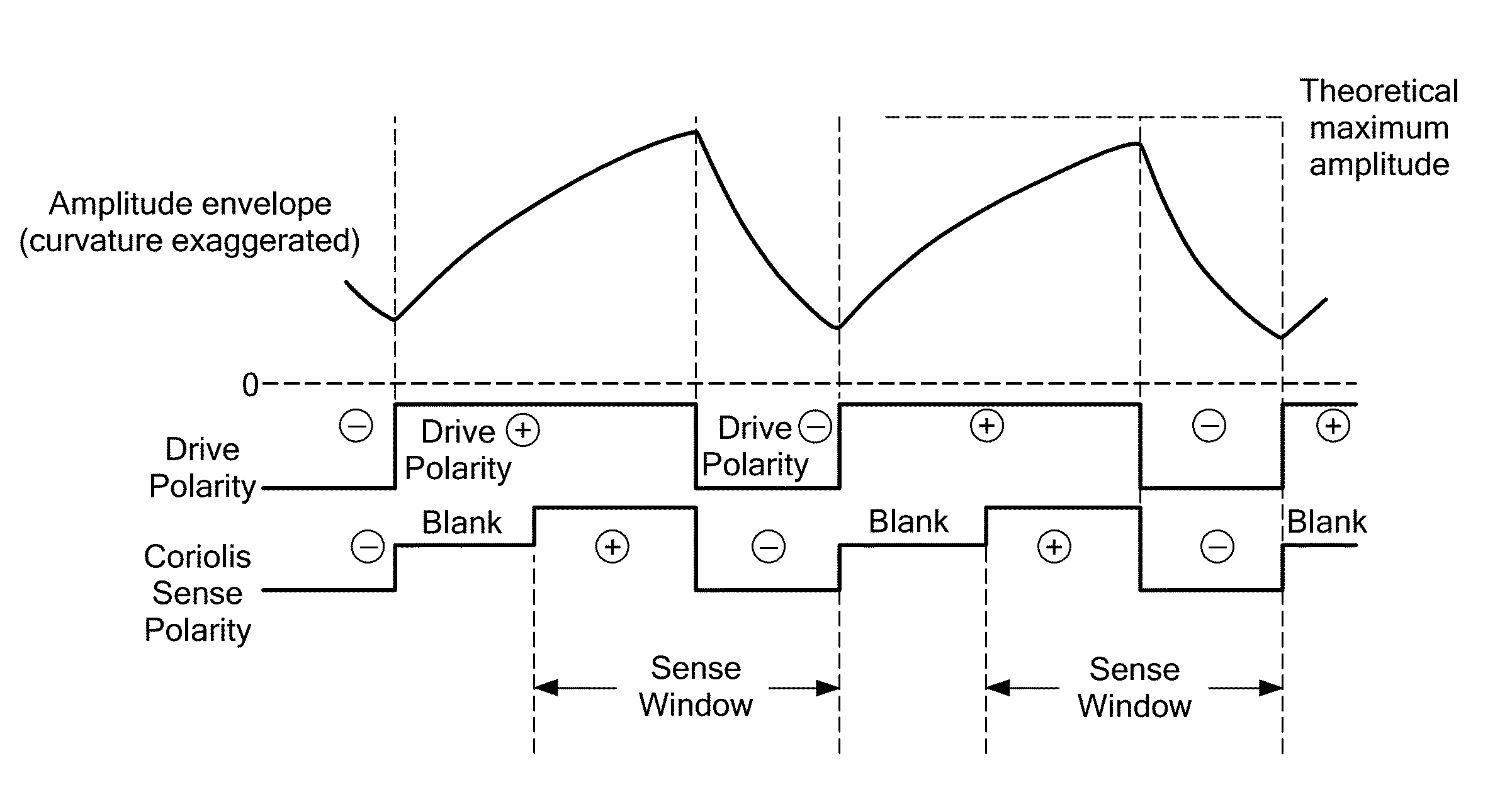
Figure 1 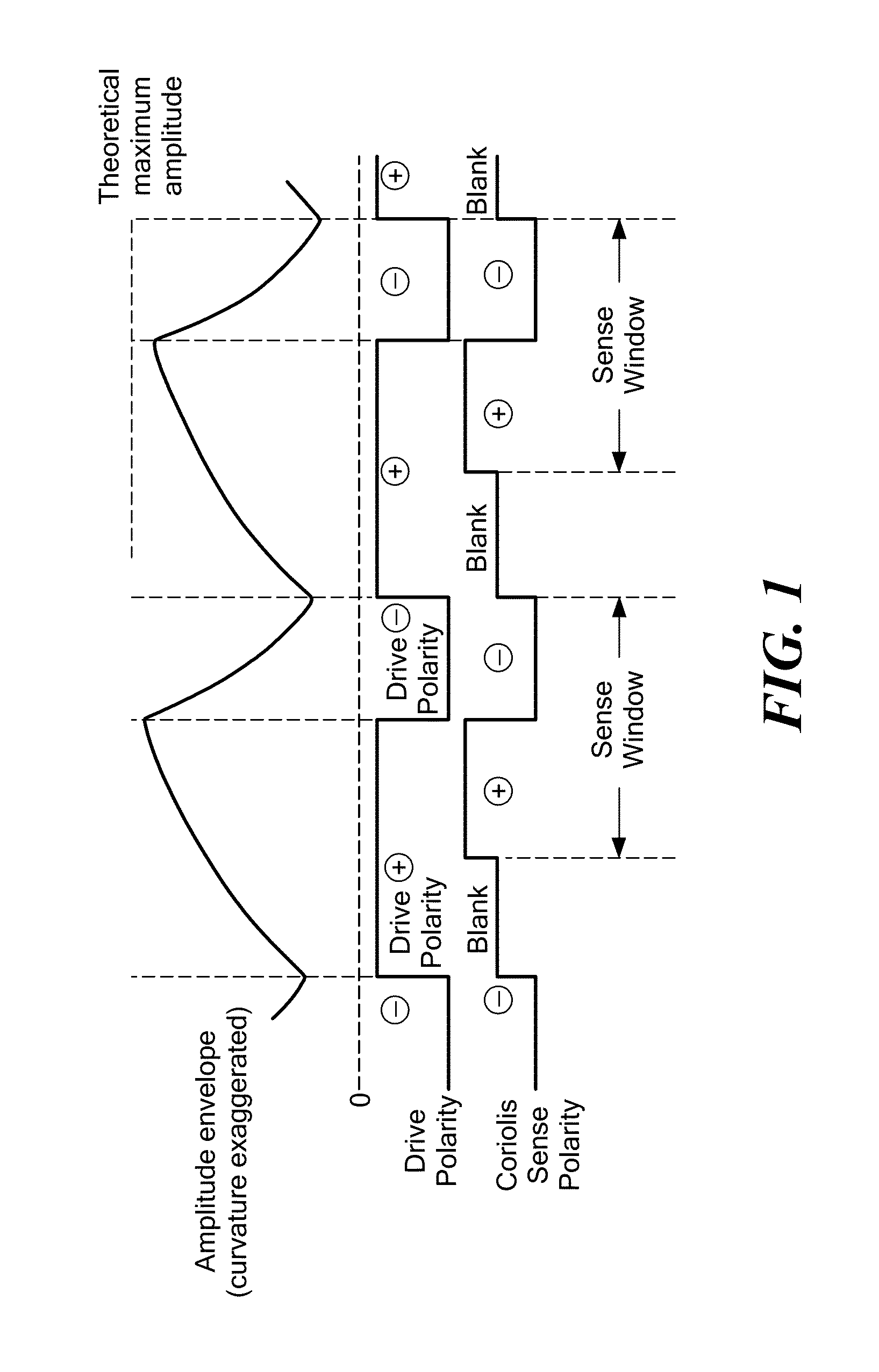
Figure 2 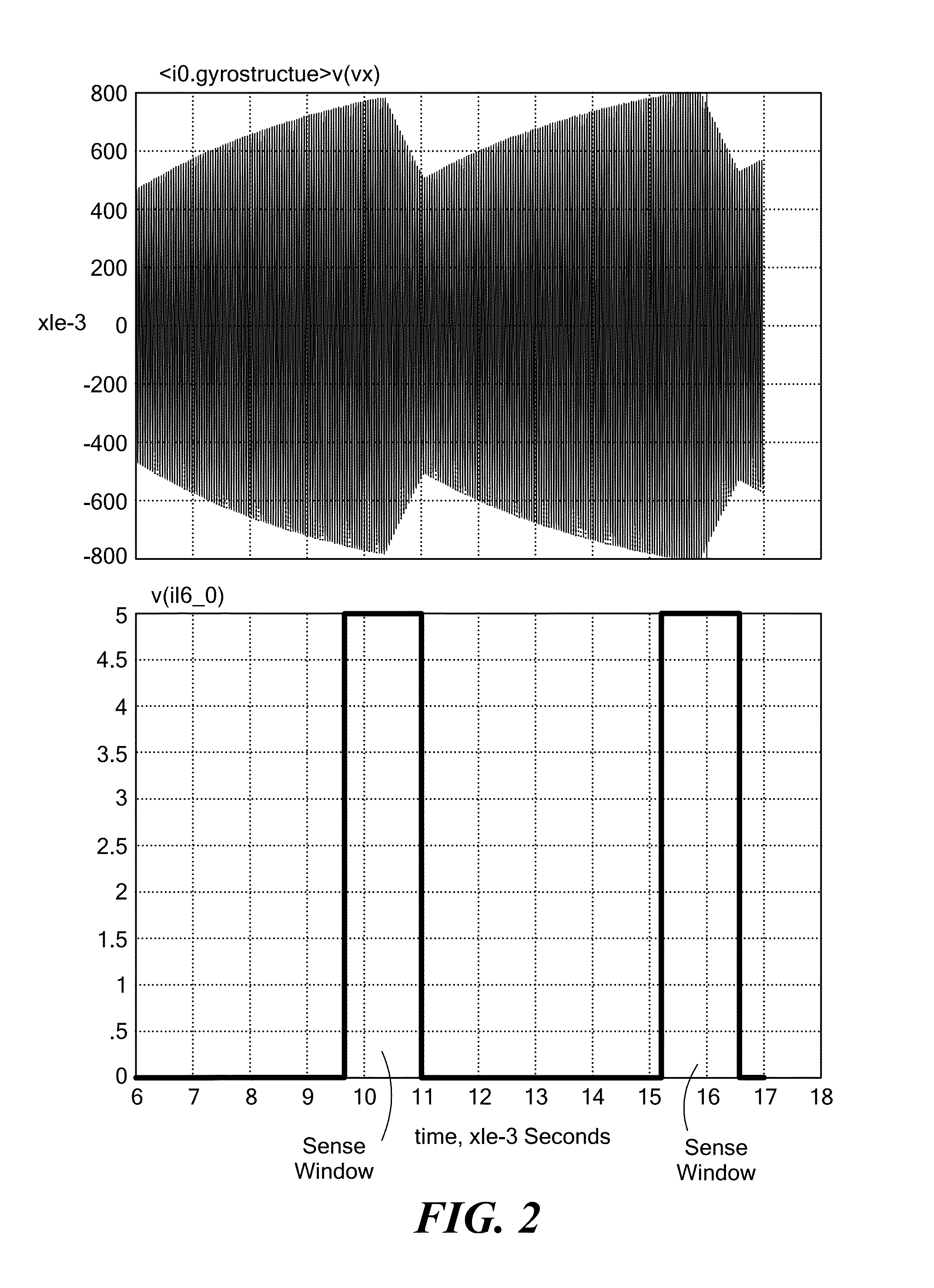
Figure 3
Abstract
Description
FIELD OF THE INVENTION
[0001] The present invention relates generally to MEMS gyroscopes, and, more particularly, to MEMS gyroscope structure and circuitry to reduce null bias errors and increase sensitivity in order to reduce or eliminate the need for calibration for many gyroscope applications.BACKGROUND OF THE INVENTION
[0002] Micromachined (MEMS) gyroscopes have become established as useful commercial items. Generally speaking, a MEMS gyroscope incorporates two high-performing MEMS devices, specifically a self-tuned resonator in the drive axis and a micro-acceleration sensor in the sensing axis. Gyroscope performance is very sensitive to such things as manufacturing variations, errors in packaging, driving, linear acceleration, and temperature, among other things. Basic principles of operation of angular-rate sensing gyroscopes are well understood and described in the prior art (e.g., Geen, J. et al., New iMEMS Angular-Rate-Sensing Gyroscope, Analog Devices, Inc., Analog Dialog 37-0...
Examples
exemplary embodiment 1
[0053]In one exemplary embodiment, during steady state operation (i.e., after initial startup of the shuttle resonance), the shuttle is driven using alternating phase (+) and anti-phase (−) drive signals such that the shuttle's amplitude (which is continually ramping up and down) increases during the phase period and decreases during the anti-phase period without reaching zero and also without reaching the theoretical maximum shuttle amplitude. Also, provided the Coriolis demodulation is co-phased with the shuttle velocity feedback, the error from drive gap mismatch is effectively reversed for half the time and effectively cancels out.
[0054]FIG. 1 schematically shows the amplitude envelope, drive polarity, sense polarity, and Coriolis sense window relationships for a first exemplary embodiment. In this exemplary embodiment, during steady state operation (i.e., after initial startup of the shuttle resonance), the shuttle is driven using alternating phase (+) and anti-phase (−) drive ...
exemplary embodiment 2
[0060]In another exemplary embodiment, the shuttle is alternately driven with a phase (+) signal for a fixed number of cycles to build the resonant motion through the essentially linear initial portion of its exponential growth and then driven with an anti-phase (−) signal for the same number of cycles to cancel that motion. In this exemplary embodiment, the amplitude of the shuttle motion periodically crosses zero. The use of equal numbers of phase and anti-phase cycles to continually ramp the amplitude of the shuttle oscillation effectively defines the shuttle Q. For example, if the drive is supplied for a duration N times the shuttle period, then the effective Q becomes πN / 2 averaged over that duration, provided the equilibrium Q is sufficiently greater than N. Since the output (sense) signal produced by the gyroscope is based on Q, this ability to define Q eliminates the need to measure Q. Thus, very low pressure, otherwise unusable because of frequency split, actually becomes a...