
Pet feces receiving and carrying device
a technology for receiving and carrying devices, which is applied in the field of hand-operating devices, can solve the problems of loosening the coupling assembly, losing the effect of fixing the angular position of the ring, loosening, swinging, deviation, etc., and achieves the effect of shortening the overall length of the rod, saving space, and improving the secureness of the ring member s
Patent Information
- Authority / Receiving Office
- US · United States
- Patent Type
- Patents(United States)
- Current Assignee / Owner
- Publication Date
- 2016-10-04
- Estimated Expiration
- Not applicable · inactive patent
Smart Images
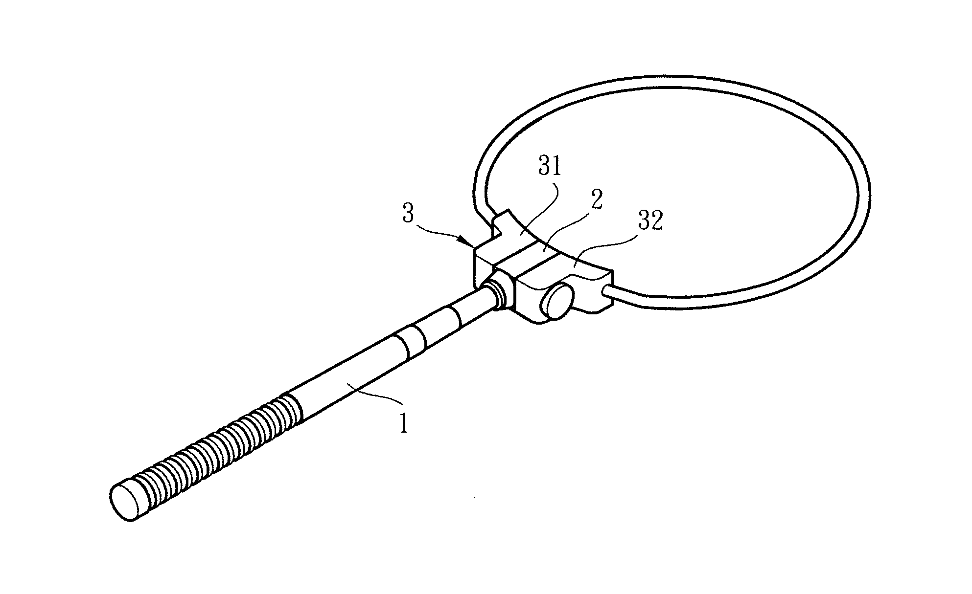
Figure 1 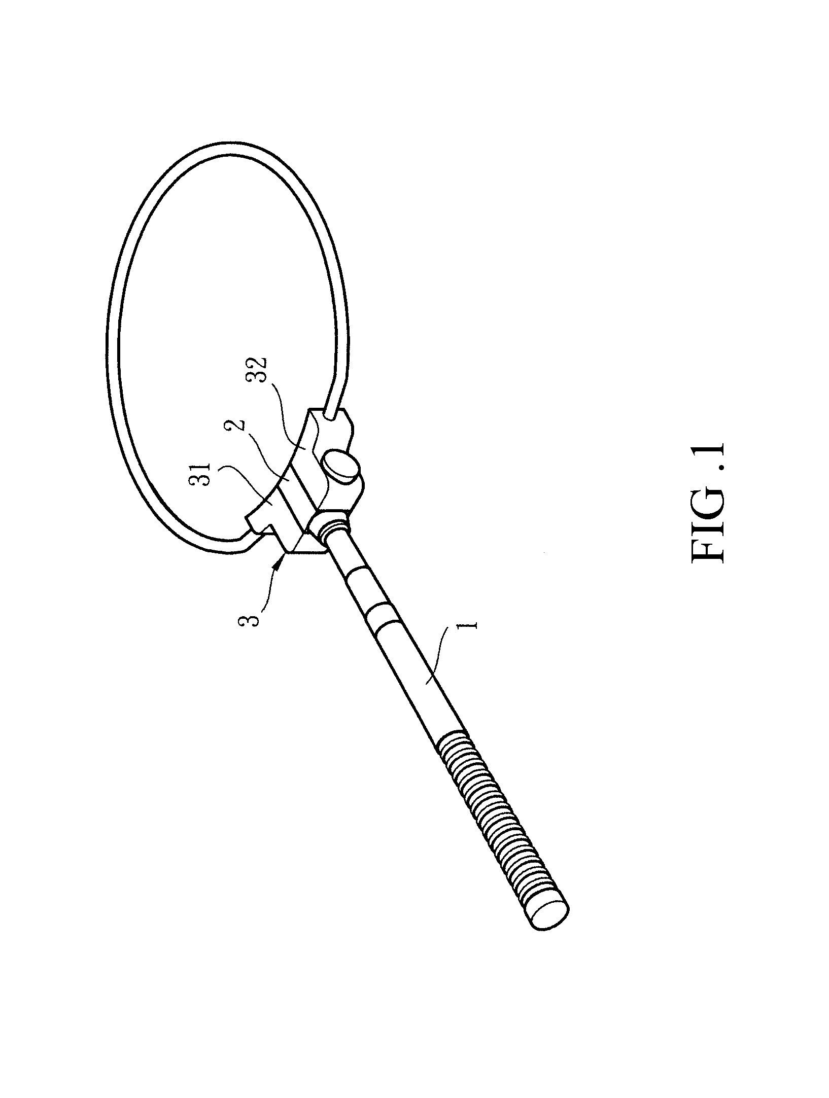
Figure 2 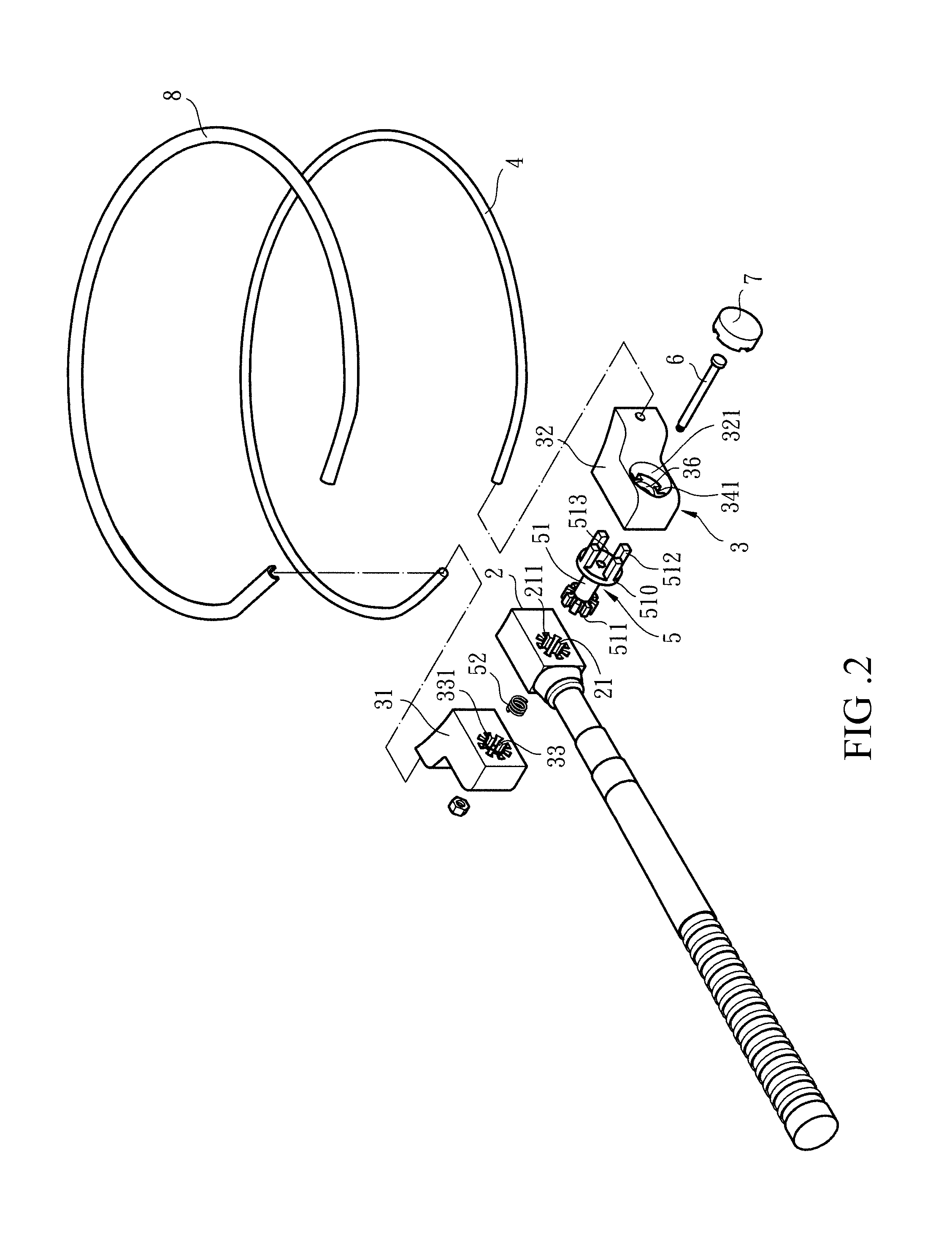
Figure 3
Abstract
Description
(a) TECHNICAL FIELD OF THE INVENTION
[0001] The present invention relates generally to a hand-operating device for manually collecting feces of pets, such as those of cats and dogs, with bare hands, and more particularly to a pet feces receiving and carrying device featuring extendibility / retractability, foldability, and adjustable angular position for receiving pet feces.(b) DESCRIPTION OF THE PRIOR ART
[0002] Various hand-operating tools or devices are available in the market for cleaning the droppings of pets. An example is illustrated in Taiwan Utility Model M491332, which discloses a feces pick-up device and generally comprises a rod having an end to which a coupling assembly is mounted. The coupling assembly comprises a ring attached thereto. To use, a bag is fit over the ring and the coupling assembly is operated to adjust an expansion angle of the ring with respect to the rod. When a pet excretes, the pet owner may hold the rod with hands to have the ring reach out to be located...
Examples
Embodiment Construction
[0018]The following descriptions are exemplary embodiments only, and are not intended to limit the scope, applicability or configuration of the invention in any way. Rather, the following description provides a convenient illustration for implementing exemplary embodiments of the invention. Various changes to the described embodiments may be made in the function and arrangement of the elements described without departing from the scope of the invention as set forth in the appended claims.
[0019]Referring to FIGS. 1-8, the drawings clearly show the present invention comprises:
[0020]a rod 1;
[0021]a pivotal joint seat 2, which is mounted to an end of the rod 1;
[0022]a rotary seat 3, which is pivotally coupled to the pivotal joint seat 2 to allow the pivotal joint seat 2 and the rotary seat 3 to relatively rotate with respect to each other;
[0023]a ring member 4, which is attached to the rotary seat 3; and
[0024]an arrestor module 5, which is arranged between the pivotal joint seat 2 and t...