
Sucker type manipulator
A manipulator and suction cup technology, applied in the field of suction cup manipulators, can solve the problems of insufficient positioning accuracy, large impact, high workpiece pressure, etc., to avoid damage and reduce costs.
- Summary
- Abstract
- Description
- Claims
- Application Information
AI Technical Summary
Problems solved by technology
Method used
Image

Examples
Embodiment 1
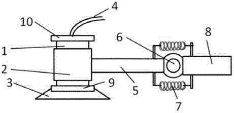
[0016] like figure 1 As shown, the suction cup type manipulator of the present embodiment includes a pick-up device and a pick-up arm 13; Shaft 1, wherein, the lower surface of the vacuum chuck 3 is provided with a flexible pad, the upper end of the sliding shaft 1 is provided with an upper limit block 10, and the lower end of the sliding shaft 1 is provided with a lower limit block 9; the pick-up arm 13 is provided with a sleeve 2 at one end, the sliding shaft 1 is set in the sleeve 2, the distance between the upper limit block 10 and the lower limit block 9 is greater than the length of the sleeve 2, the The sleeve 2 is arranged between the upper limit block and the lower limit block 9; when the sliding shaft 1 is opposite to the force direction of the sleeve 2, the sliding shaft 1 is inside the sleeve 2 slide.
[0017] When the suction cup-type manipulator of this embodiment picks up the workpiece, the suction cup descends. After touching the workpiece, the pick-up arm 13...
Embodiment 2
[0019] On the basis of Embodiment 1, the pick-up arm 13 includes a mechanical section 8 and a sleeve section 5; the mechanical section 8 and the sleeve section 5 are hinged, and the hinge shaft 6 is horizontally arranged, and the upper side of the hinge shaft 6 and A spring 7 is arranged on the lower side, and the two ends of the spring 7 are respectively connected with the mechanical section 8 and the sleeve section 5 . The sleeve section 5 is connected with the mechanical section 8 through the rotating shaft and the spring 7, so that the sleeve section 5 and the mechanical section 8 can produce a certain angle. Since the angle of the pick-up device and the sleeve section 5 changes synchronously, the setting here can Change the angle of the pick-up device to adapt to the actual position of the workpiece and the plane of the workpiece table. Because the spring 7 is used to tighten the two ends, the angle of the suction cup can be automatically changed when the pick-up device i...
Embodiment 3
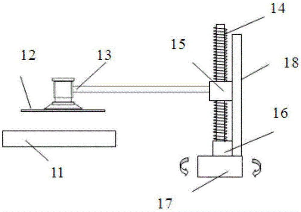
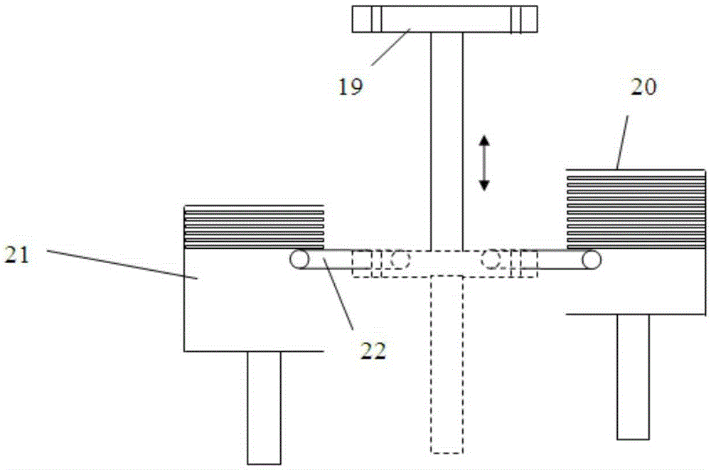
[0021] like Figure 2-3 As shown, in addition to the structure of the above-mentioned embodiments, the suction cup robot arm of this embodiment also includes a slider 15 connected to the other end of the picking arm 13, a slide rail 18 forming a sliding pair with the slider 15, A lead screw 14 that cooperates with the slider 15 to form a ball screw pair, a driving device 16 that drives the lead screw 14 to rotate, and a rotary table 17 connected to the bottom end of the lead screw 14 and the slide rail 18, wherein , the lead screw 14 and the slide rail 18 are all arranged vertically. The lower limit block is provided with a displacement sensor that senses the distance of the sleeve.
[0022] The specific implementation steps of this embodiment will be described with respect to the workflow of the sucker-type manipulator in this embodiment in the laser annealing process for semiconductor wafer 12 processing:
[0023] The entry / exit table 19 is located at the entry / exit positi...
PUM
 Abstract
Description
Claims
Application Information