
Rotational-flow static-state mixed aeration apparatus
A technology of aeration device and static mixing, applied in water aeration, water treatment parameter control, water/sludge/sewage treatment, etc., can solve the problems of large air supply resistance, small service area, low dissolved oxygen efficiency, etc. To achieve the effect of small resistance loss, reducing operating costs and improving utilization
Patent Information
- Authority / Receiving Office
- CN · China
- Current Assignee / Owner
- Publication Date
- 2018-05-15
- Estimated Expiration
- Not applicable · inactive patent
Smart Images
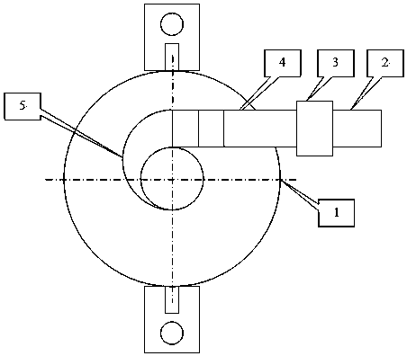
Figure 1 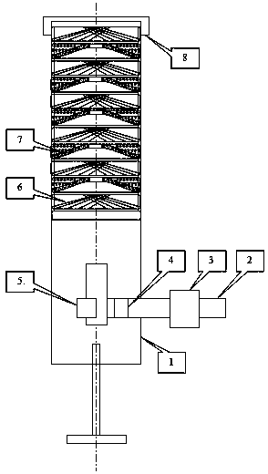
Figure 2 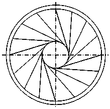
Figure 3
Abstract
Description
technical field
[0001] The invention relates to the technical field of sewage treatment aeration equipment, in particular to a cyclone static mixing aeration device. Background technique
[0002] Aerobic treatment is a process unit commonly used in sewage treatment technology. The activated sludge microorganisms in the sewage of the aerobic pool degrade organic pollutants under the condition of air supply and oxygenation, so as to achieve the purpose of removing various organic pollutants.
[0003] The aerator is an essential equipment for aeration and oxygenation in the aerobic process of sewage treatment. The blower generates pressure air, which is transported to the aerator through pipelines, and the oxygen is evenly distributed in the sewage to provide the oxygen source required by microorganisms. When the air bubbles formed by the aerator come into contact with the sewage, the oxygen in the air bubbles is dissolved in the water. The indicator for evaluating the effect ...
Examples
Embodiment 1
[0021] like Figure 1~6 As shown, the embodiment of the present invention provides a swirl static mixing aeration device, which includes a cylindrical shell (1), an air inlet pipe joint (2), a one-way valve (3), a square air inlet guide pipe (4 ), intake volute deflector (5), rotating deflector (6), spiral groove type air bubble cutting device (7), top fixing ring (8); the inlet pipe joint (2), one-way The valve (3), the square air intake guide pipe (4), and the intake volute deflector (5) are connected in sequence, installed in the lower part of the cylindrical shell (1), and the outlet pipe of the intake volute deflector (5) The center coincides with the center of the cylindrical shell (1); the rotating deflector (6) and the spiral groove type air bubble cutting device (7) are alternately installed on the upper part of the cylindrical shell (1), and the top fixed ring (8) After pressing the rotating deflector (6) and the spiral groove type air bubble cutting device (7), fas...