
Concrete hole wall scrabbling device
A technology of concrete and hole wall, which is applied in the direction of construction, building structure, and building material processing, etc. It can solve the problems that cannot be well adapted to the site construction requirements, it is difficult to control the chisel strength, and the chisel density cannot be adjusted, etc., to achieve Reduce the amount of manual labor, facilitate the construction quality, and have the effect of ingenious structure
Patent Information
- Authority / Receiving Office
- CN · China
- Current Assignee / Owner
- Publication Date
- 2020-07-28
Smart Images
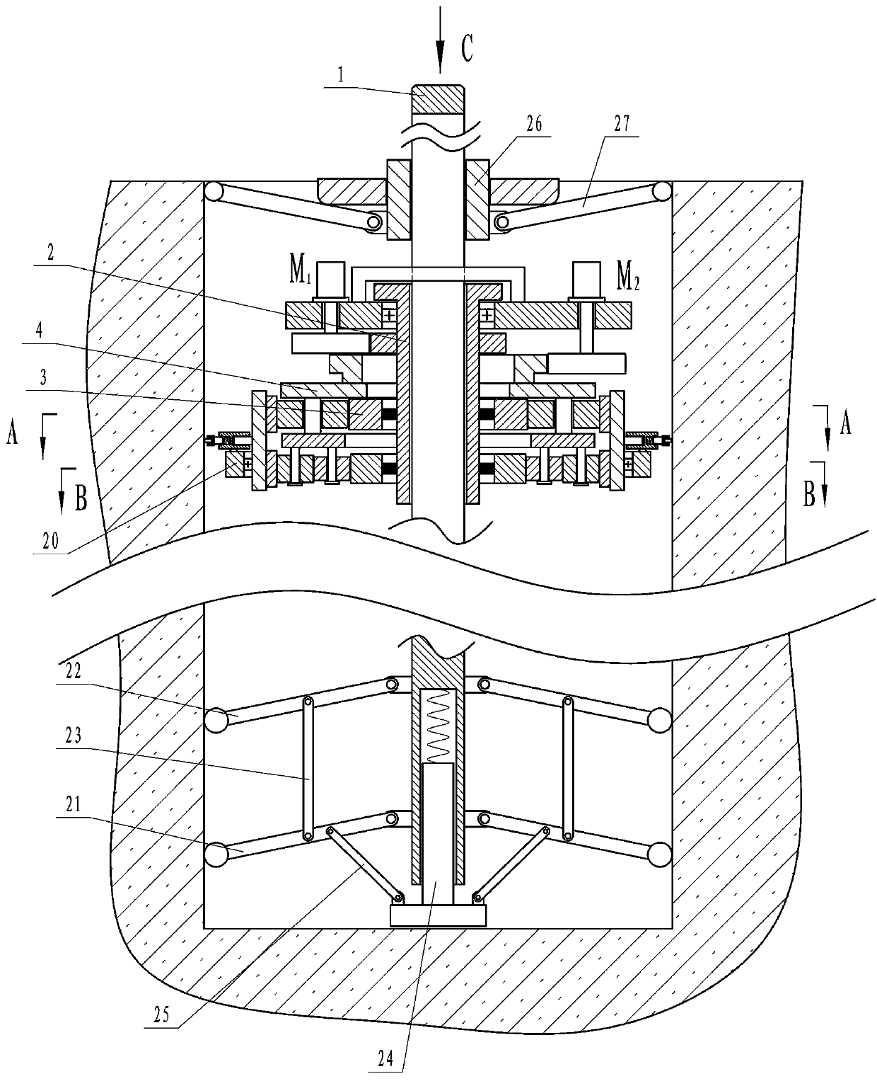
Figure 1 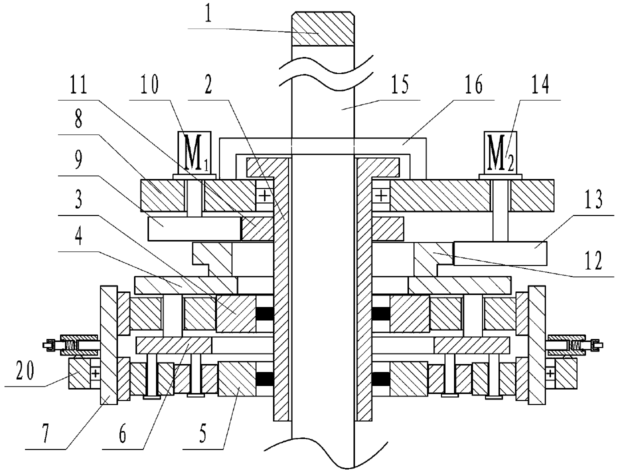
Figure 2 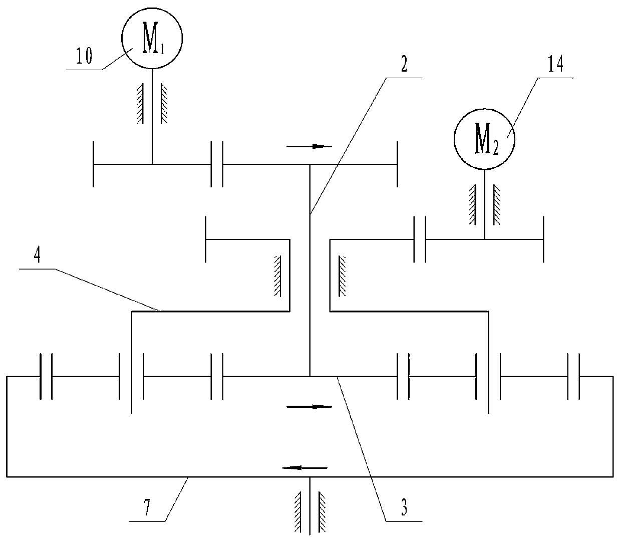
Figure 3
Abstract
Description
technical field
[0001] The invention relates to the technical field of construction machinery, in particular to a concrete hole wall chipping device. Background technique
[0002] At present, during construction work, there are often reserved holes on the building surface for the installation and use of subsequent equipment or parts. In order to ensure that the parts can be fixed firmly, the side walls of the holes are usually roughened before concrete sealing. For example, the construction of anti-floating anchor rods.
[0003] In the prior art, most chisel machines can only deal with the exposed surface. For the inner wall of the hole after concrete drilling, it is impossible to chisel it. The traditional hole chiseling method is to use a steel sheet to beat in the hole to damage the hole wall. Make it rough and increase the friction force. With this method of hole processing, the steel sheet can swing in a limited angle in the hole, and the processing point is limited to...
Examples
Embodiment Construction
[0020] The specific implementation manners of the present invention will be further described in detail below in conjunction with the accompanying drawings.
[0021] Depend on Figure 1 to Figure 10 Given, the present invention includes a vertical and non-rotatable screw 1, the screw 1 is placed in the concrete reserved hole and coaxial with it, the screw 1 is sleeved with a threaded tube 2 that can actively rotate, and the threaded tube 2 and the screw 1 Through screw connection, the lower end of the threaded pipe 2 is equipped with a first planetary gear train, wherein the first sun gear 3 in the first planetary gear train is set on the lower end of the threaded pipe 2, and the threaded pipe 2 can drive the first sun gear 3 only when it rotates forward Rotation, the first planetary carrier 4 in the first planetary gear train can actively rotate, the first sun gear 3 in the first planetary gear train is opposite to the rotation direction of the first ring gear; there is a sec...