

Method for preventing metal materials from being scratched on tube wall in tubular annealing furnace
A technology of metal materials and annealing furnaces, applied in the direction of metal processing equipment, furnaces, furnace types, etc., can solve the problem of the same force on the outer surface of the metal strip body
Patent Information
- Authority / Receiving Office
- CN · China
- Current Assignee / Owner
- Publication Date
- 2021-04-27
Smart Images
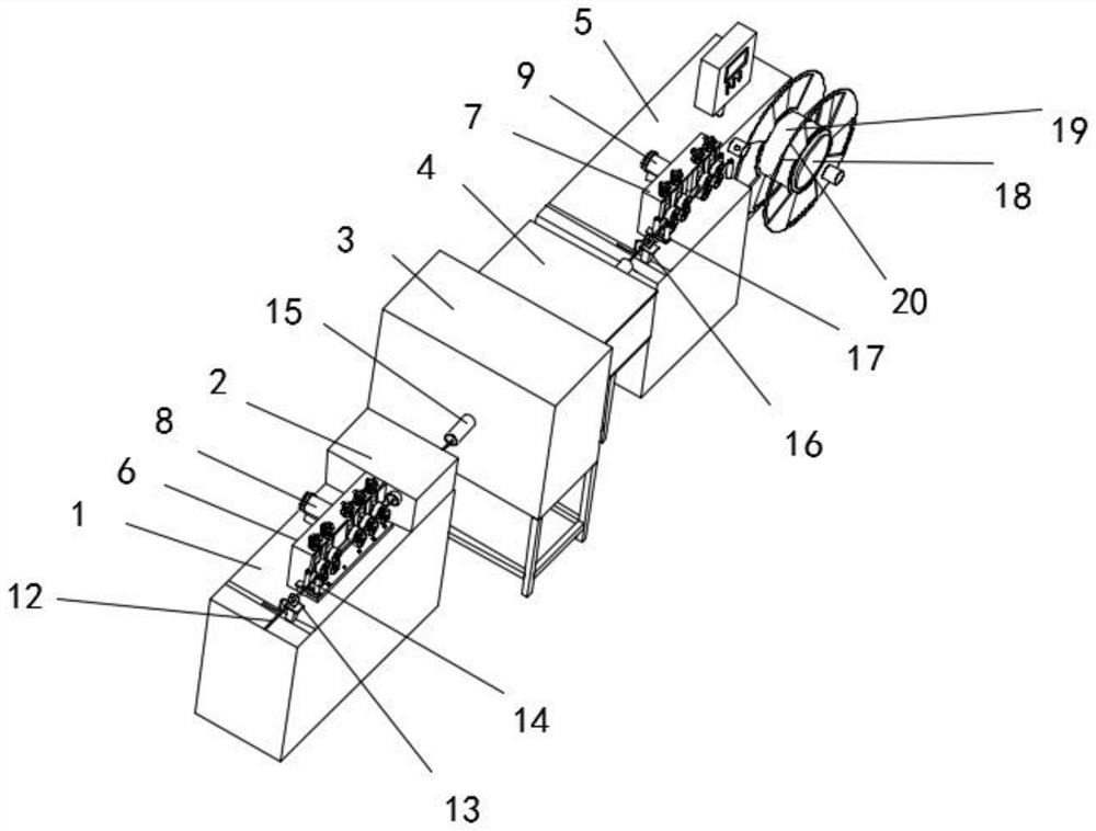
Figure 1 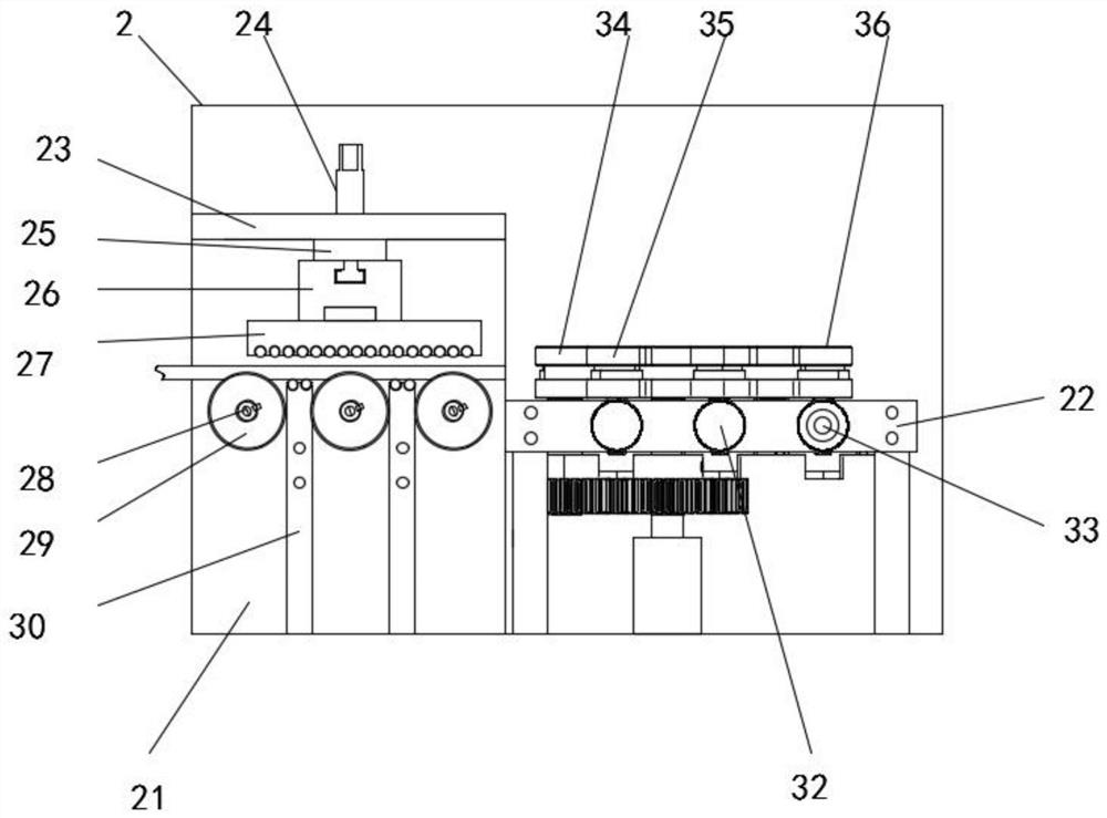
Figure 2 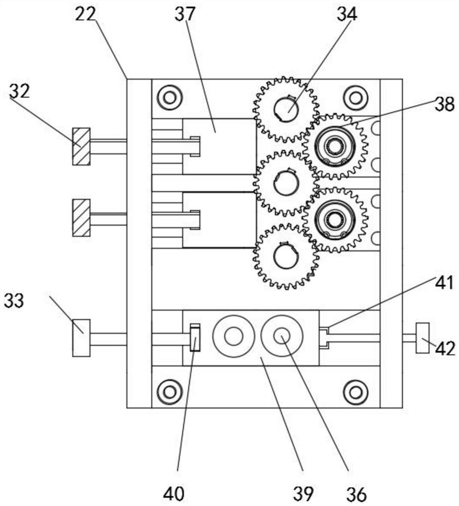
Figure 3
Abstract
Description
technical field
[0001] The invention relates to the technical field of metal materials, in particular to a method for preventing metal materials from being scratched on tube walls in a tube annealing furnace. Background technique
[0002] At present, the metal processing market (CNC processing, etc.) has an increasing demand for metal profiles in order to improve processing efficiency, save costs, and reduce losses. ) requirements are getting higher and higher, which puts forward higher requirements for the control of metal materials in the process of processing. Annealing is an indispensable link. The quality of annealing is related to the surface quality, hardness stability and profile of stainless steel profiles The size of the residual stress.
[0003] Normal tubular annealing generally consists of a feeding part, a cleaning part, an annealing furnace heating part, an annealing furnace cooling part, and a material receiving part. The furnace tubes in the annealing furna...
Examples
Embodiment 1
[0034] Such as Figure 1-5 As shown, the method for preventing metal material from scratching the tube wall in the tube annealing furnace comprises the following steps:
[0035] Step 1: Take a roll of strip-shaped metal material, which is the metal strip body 12;
[0036] Step 2: Pass the metal bar body 12 through the inside of the first ring encoder 13 into the annealing device, and control the first ring encoder 13 to slide on the upper surface of the first support base 1 through the bar-shaped groove 1, so that the metal bar body 12 Pass through the first limit stop post 14 to the position between the first tension wheel 66 and the second tension wheel 68, start the first drive motor 8, and drive the third rotating rod 70 to rotate, the outer surface of the third rotating rod 70 The socketed gear four is engaged with the gear three socketed on the outer surface of the second rotating rod 67 near the rear end, thereby driving the second rotating rod 67 to rotate, and then d...