
Attitude angle detecting apparatus
a detection apparatus and angle technology, applied in position fixation, wave based measurement systems, instruments, etc., can solve the problems of inability to immediately obtain the attitude angles, the degree of deterioration of the estimated attitude angles is considerably affected, and the above-mentioned apparatus cannot measure the carrier phases, etc., to achieve the effect of instant calculation of correct integer ambiguities, rapid detection of heading and attitude, and high precision
Patent Information
- Authority / Receiving Office
- US · United States
- Patent Type
- Patents(United States)
- Current Assignee / Owner
- Publication Date
- 2004-09-14
- Estimated Expiration
- Not applicable · inactive patent
Smart Images
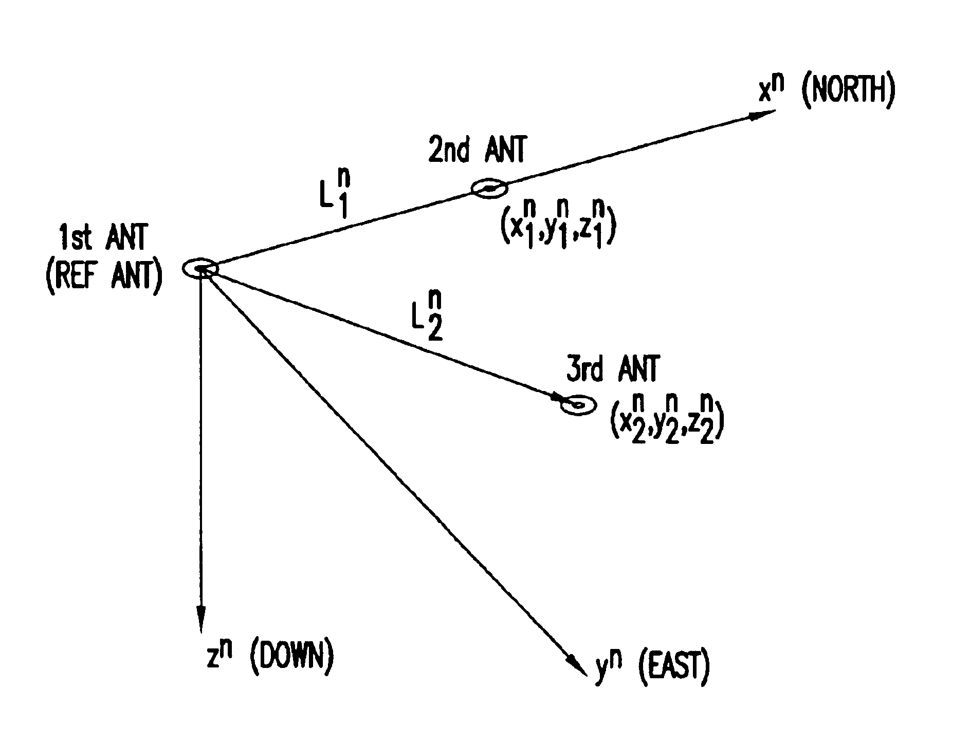
Figure 1 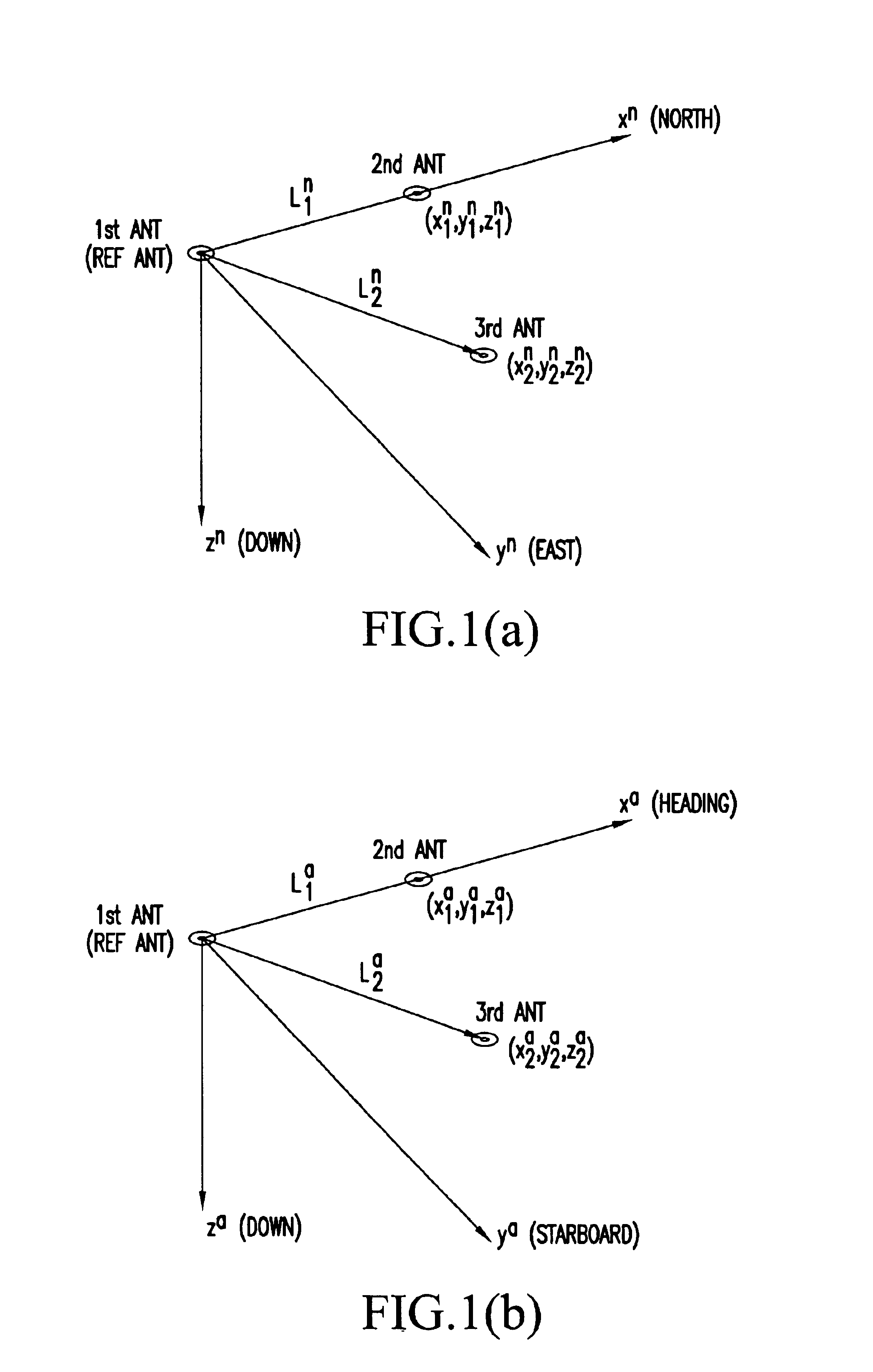
Figure 2 
Figure 3
Abstract
Description
1. Field of the InventionThis invention relates to an attitude angle detecting apparatus for detecting the heading and attitude of a mobile unit, such as an aircraft or a ship.2. Description of the Prior ArtThere exist conventionally used attitude angle detecting apparatus for detecting the heading and attitude of a mobile unit.One type of such apparatus receives radio waves transmitted from a plurality of position-fixing satellites with multiple antennas located at specific positions of a mobile unit, one of the antennas being used as a reference antenna, measures phases of carrier signals of the radio waves, and determines relative positions of the antennas other than the reference antenna with respect to the reference antenna to determine the heading and attitude of a mobile unit.Another type of such apparatus determines the attitude of a mobile unit by use of an angular velocity sensor like a rate gyro for measuring the turning rate of a mobile unit.The aforementioned apparatus ...
Examples
Embodiment Construction
First, an antenna coordinate system, a local coordinate system and coordinate transformation between these two coordinate systems are explained referring to FIGS. 1A and 1B.
FIG. 1A shows an antenna layout depicted in the local coordinate system, in which the x, y and z axes represent north, east and vertical directions, respectively, with the position of a reference antenna (first antenna) located at an origin, for instance.
In FIG. 1A, a point shown by coordinates (x.sub.1.sup.n, y.sub.1.sup.n, z.sub.1.sup.n) is the position of a second antenna, a point shown by coordinates (x.sub.2.sup.n, y.sub.2.sup.n, z.sub.2.sup.n) is the position of a third antenna, L.sub.1.sup.n is a baseline vector taken from the first antenna to the second antenna, and L.sub.2.sup.n is a baseline vector taken from the first antenna to the third antenna. The superscript "n" written to the right of the values of the coordinates and the baseline vectors indicates that these coordinates and baseline vectors are ...