Fuel pump with a guided tappet assembly and methods for guiding and assembly

a fuel pump and tappet technology, which is applied in the direction of fuel injecting pumps, machines/engines, positive displacement liquid engines, etc., can solve the problems of the pins that are inserted through an opening in the pump housing can actually become loose and back out sufficiently, so as to reduce contact stress and reduce contact stress

Active Publication Date: 2007-12-25
CUMMINS INC
View PDF24 Cites 28 Cited by
  • Summary
  • Abstract
  • Description
  • Claims
  • Application Information

AI Technical Summary

Benefits of technology

[0010]Thus, one aspect of the present invention is in providing a fuel pump including a reciprocating tappet assembly that is guided by a guide key with a head that reduces the contact stress exerted on the guide key, and distributes bending stress to the bore wall surface of the fuel pump to improve the durability and reliability of the fuel pump.
[0011]Another aspect of the present invention is in providing a method for guiding a reciprocating tappet assembly in a fuel pump that maintains the rotational positioning of the tappet assembly relative to a camshaft lobe.
[0012]Still another aspect of the present invention is in providing a method of assembling a fuel pump that includes a guide key in which proper assembly of the guide key is facilitated.
[0015]In accordance with another aspect of the present invention, a method for guiding a reciprocating tappet assembly in a fuel pump is provided, the method includes providing a fuel pump housing with a cylindrical bore having a central axis and being at least partially defined by a bore wall surface of the fuel pump housing, forming a receiving hole in the fuel pump housing that is open into the cylindrical bore, and providing a guide key with a head that extends into the cylindrical bore, the head having an outer dimension along the central axis of the cylindrical bore that is larger than a dimension of the receiving hole along the central axis. The method also includes inserting at least a portion of the guide key into the receiving hole, and providing a tappet assembly received in the cylinder bore, the tappet assembly including an outer peripheral surface and an elongated key slot longitudinally extending parallel to the central axis of the cylinder bore. The rotational positioning of the tappet assembly is maintained by receiving the head of the guide key in the elongated key slot of the tappet assembly.
[0016]In accordance with one embodiment, the head may be provided with at least one extension that is slidably received in the elongated key slot to reduce contact stress exerted on the head as the tappet assembly is reciprocally displaced in the cylindrical bore. The head of the guide key may also be provided with a support surface, and the method may also include at least partially distributing bending stress exerted on the guide key to the bore wall surface through the support surface as the tappet assembly is reciprocally displaced in the cylindrical bore. In accordance with another embodiment, the method further includes pressing in the body of the guide key into the receiving hole.
[0017]In yet another aspect of the present invention, a method of assembling a fuel pump is provided, the method including providing a fuel pump housing with a cylindrical bore having a central axis and being at least partially defined by a bore wall surface of the fuel pump housing, forming a receiving hole in the fuel pump housing that is open into the cylindrical bore, and providing a guide key having a head, the head having an outer dimension along the central axis of the cylindrical bore that is larger than a dimension of the receiving hole along the central axis. The method also includes inserting the body of the guide key into the receiving hole in a manner that the head of the guide key extends into the cylindrical bore. The method further includes providing a tappet assembly including an outer peripheral surface and an elongated key slot extending longitudinally on the outer peripheral surface, and inserting the tappet assembly into the cylindrical bore with the key slot being positioned to receive the head of the guide key therein to maintain the rotational positioning of the tappet assembly. The head may be provided with at least one extension that is slidably received in the elongated key slot to reduce contact stress exerted on the head as the tappet assembly is reciprocally displaced in the cylindrical bore. The head of the guide key may be provided with a support surface, and the method may also include at least partially distributing bending stress on the guide key to the bore wall surface through the support surface as the tappet assembly is reciprocally displaced in the cylindrical bore.

Problems solved by technology

The above described fuel pumps that implement the tappet guides of the prior art have been found to fail for various reasons.
In particular, during high speed or abusive use conditions, the pins that are inserted through an opening in the pump housing such as that described in U.S. Pat. No. 5,415,533 issued to Egger et al. can actually become loose and back out sufficiently.
This can cause the tappet assembly to rotate in the bore so that the centerlines of the roller and the cam lobe no longer align.
Such rotation of the tappet assembly generally results in catastrophic failure of the fuel pump.
The disadvantage of such system and method of inserting the pin into a blind receiving hole is that it is difficult to accurately control the extent to which the pin is inserted into the receiving hole, and the extent to which the pin extends into the cylindrical bore.
If the pin protrudes too far out or too little, the guiding function of the pin may be impeded.
Because the receiving hole is blind, the insertion of the pin into the receiving hole with the desired amount of the pin protruding is difficult to attain.
In addition, over time, the outer periphery of the pin, the guide slot of the tappet, and / or the opening of the receiving hole can wear due to the bending and contact stresses caused by the reciprocating movement of the tappet assembly.
This causes bending and contact stresses, and corresponding wear, in the peripheral surface of the pin and / or the guide slot itself.
This wear can also lead to failure of the fuel pump.

Method used


Image

  • Fuel pump with a guided tappet assembly and methods for guiding and assembly
  • Fuel pump with a guided tappet assembly and methods for guiding and assembly
  • Fuel pump with a guided tappet assembly and methods for guiding and assembly

Examples


Embodiment Construction

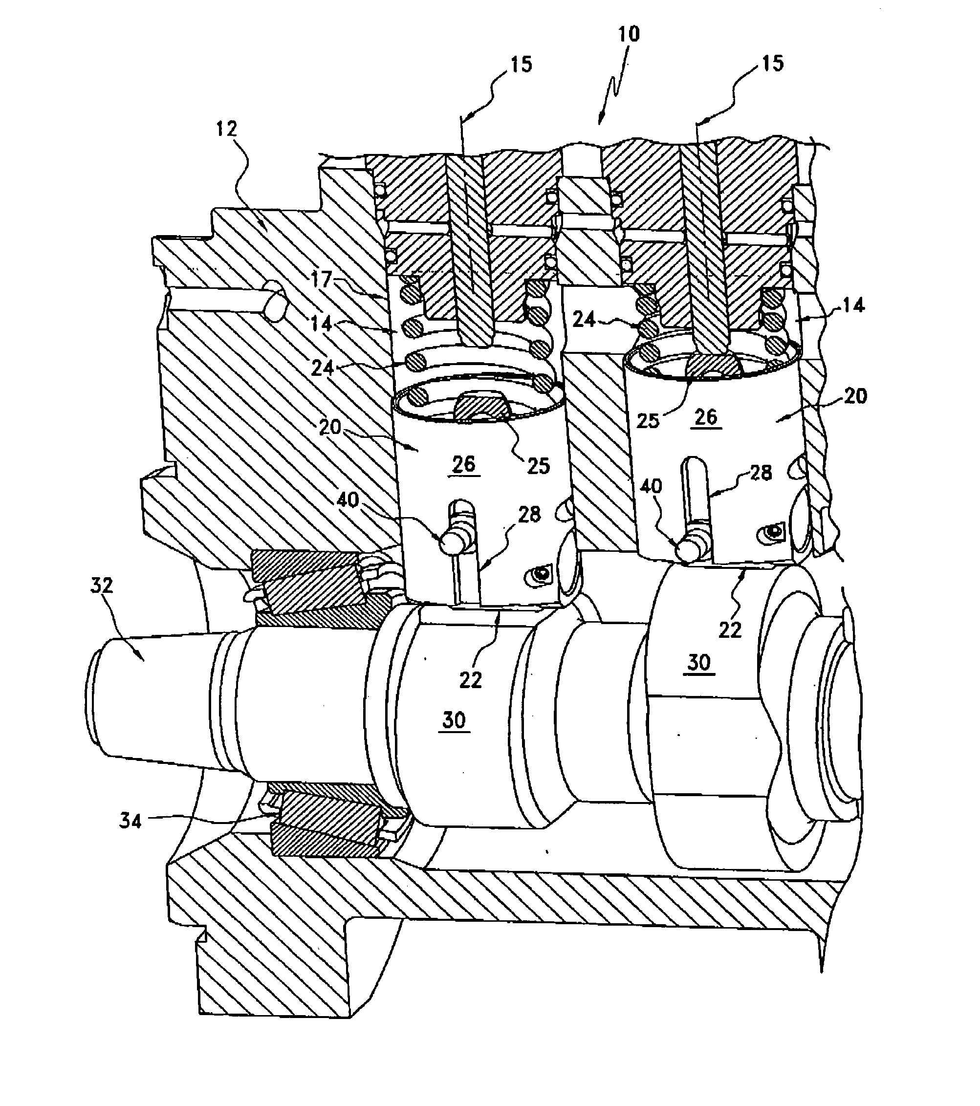
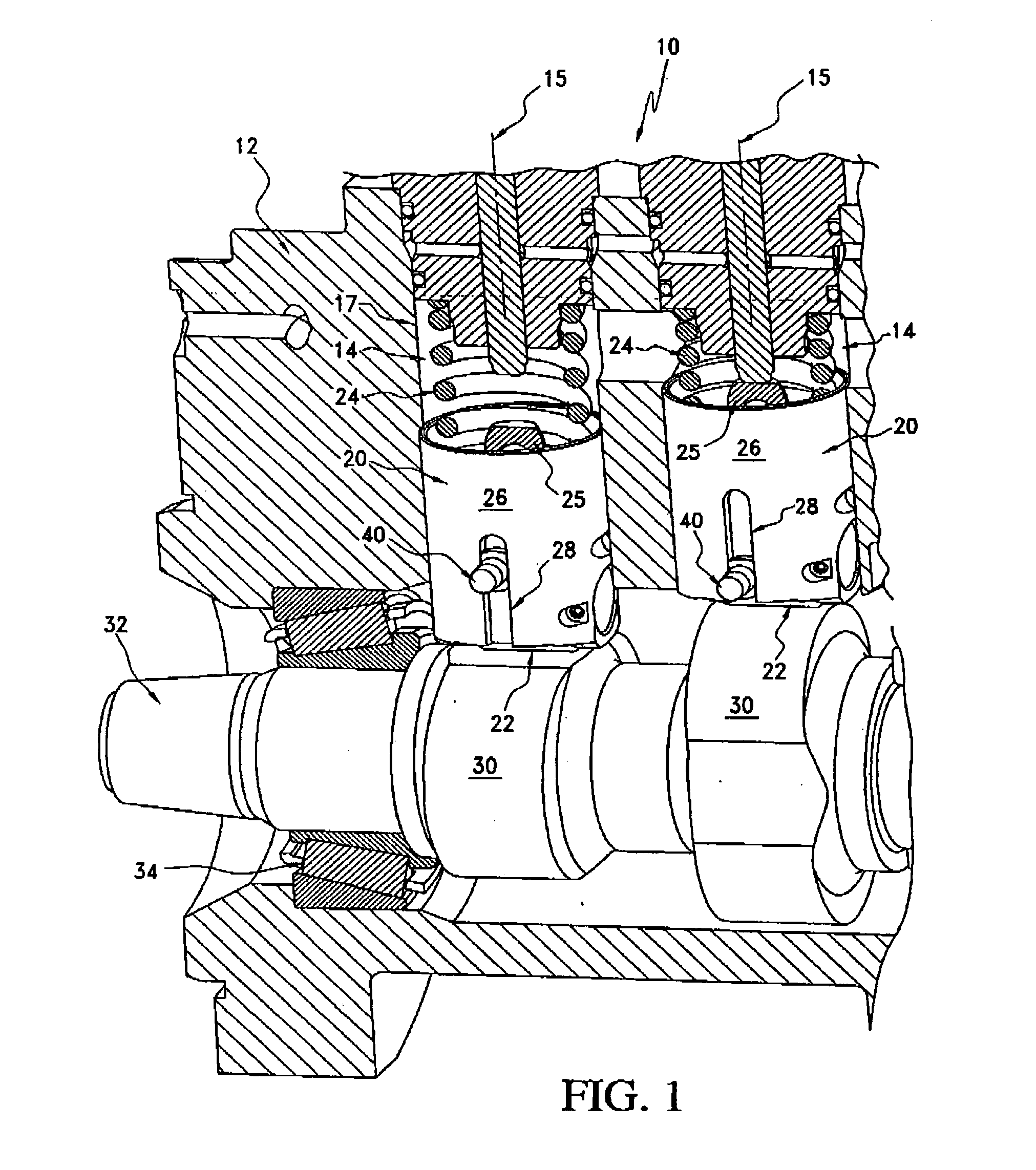
[0024]FIG. 1 illustrates a partial cross-sectional view of a fuel pump 10 in accordance with one example embodiment of the present invention. As will be described in further detail below, the fuel pump 10 implements a novel method for guiding a reciprocating tappet assembly to maintain the rotational position of the tappet assembly. The features of the fuel pump 10 as described in further detail below, enhances the fuel pump's durability and reliability as compared to conventional fuel pumps. The specific details of the structure and operation of fuel pumps are generally known in the art, and are not critical for understanding the present invention. Correspondingly, detailed discussions relative to the fuel pump 10 itself, and its functions, are omitted herein.

[0025]The fuel pump 10 as shown in FIG. 1 includes a fuel pump housing 12 with cylindrical bores 14 that have a central axis 15 and corresponding bore wall surfaces 17 that at least partially define the cylindrical bores 14. R...


PUM


Abstract

A fuel pump for an internal combustion engine including a fuel pump housing, a cylindrical bore having a central axis and being defined by a bore wall surface, a receiving hole formed in the housing, and a tappet assembly received in the cylinder bore. The tappet assembly includes an outer peripheral surface with an elongated key slot longitudinally extending parallel to the central axis. A guide key partially received in the receiving hole is provided, the guide key including a head that extends into the cylindrical bore to engage the elongated key slot of the tappet assembly. The head has an outer dimension that is larger than a dimension of the receiving hole along the central axis. Methods for guiding a reciprocating tappet assembly in a fuel pump and assembling a fuel pump are also provided.

Description

TECHNICAL FIELD[0001]This invention relates to a fuel pump with a guided reciprocating tappet assembly, and methods for guiding a tappet assembly and assembling a fuel pump.BACKGROUND OF THE INVENTION[0002]Various fuel pumps that are used to provide fuel to internal combustion engines are driven by a lobed camshaft that displaces a tappet assembly with a roller that rolls along the cam lobe. The reciprocating motion of the tappet assembly generates fuel flow that is used by the internal combustion engine to generate power. These types of fuel pumps are popular in modern fuel systems, and are frequently used in common rail fuel systems applications where high fuel pressures are required. In such fuel pumps, the reciprocating tappet assembly is guided so that the centerline of the roller and the centerline of the camshaft are maintained in an aligned position with respect to each other.[0003]Conventional fuel pumps utilize a solid dowel pin that is pressed into the housing of the fuel...

Claims


Application Information

Patent Timeline
Patent Type & Authority Patents(United States)
IPC IPC(8): F02M37/04
CPCF02M59/102F04B1/0439F04B1/02F02M2200/8015F01L2307/00
Inventor SHAULL, ANTHONY A.THAYER, WESLEY R.
Owner CUMMINS INC
Why Eureka
Try Eureka