
Method and apparatus for interference cancellation
a technology of interference cancellation and interference signals, applied in the field of interference cancellation, can solve the problems of reducing and interference signals that fall within the receive frequency band are usually a bigger problem, so as to reduce the performance requirement of a diplexer, reduce the cost, and reduce the performance required of a diplexer.
Patent Information
- Authority / Receiving Office
- US · United States
- Patent Type
- Patents(United States)
- Current Assignee / Owner
- Publication Date
- 2011-10-11
Smart Images
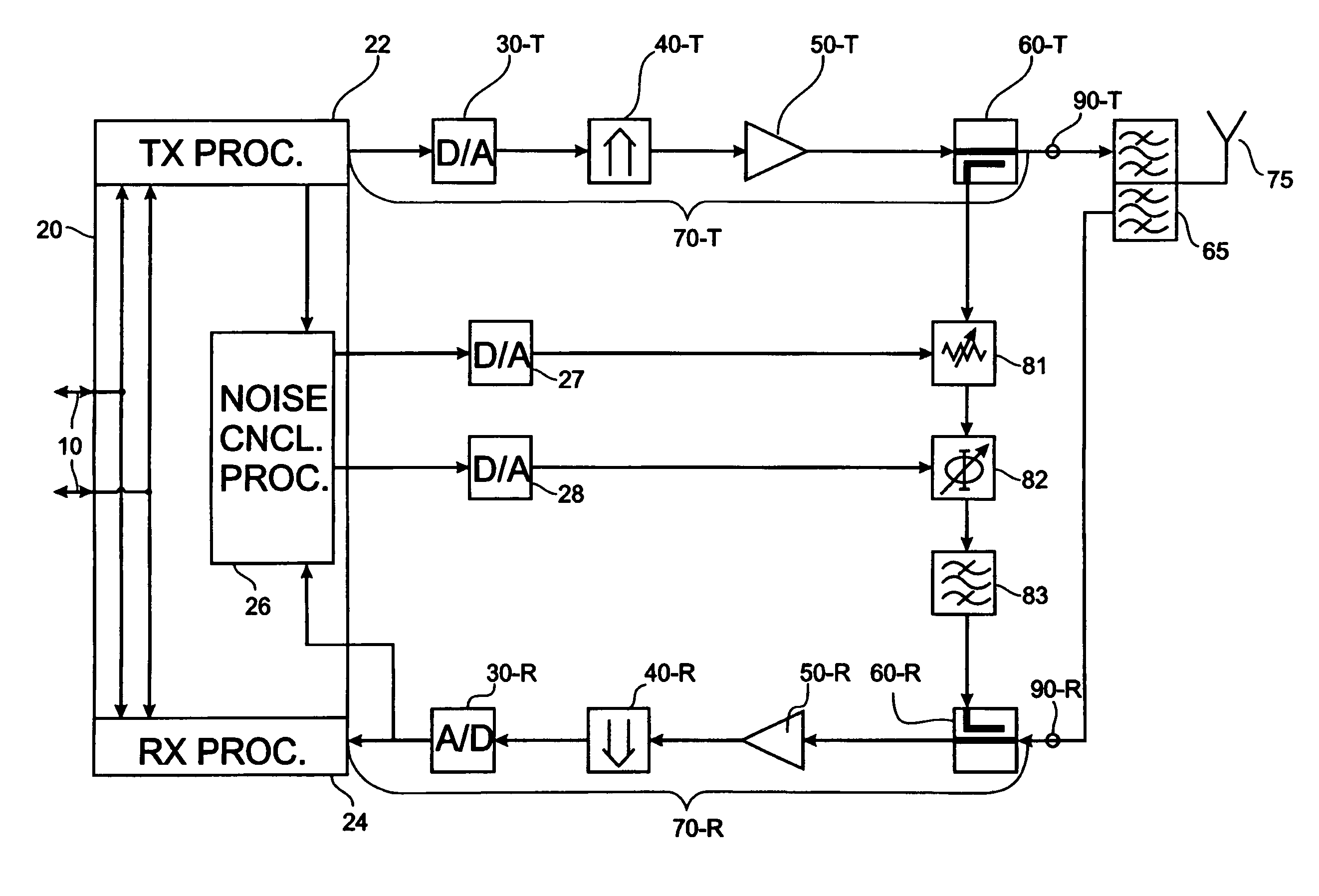
Figure 1 
Figure 2 
Figure 3
Abstract
Description
FIELD OF THE INVENTION
[0001] The application relates to an interference canceller in a radio transceiver. The application also relates to a method for interference cancellation in a radio transceiver.
[0002] The application further relates to a computer program product enabling a processor to carry out the method for interference cancellation and to a computer program product useable for the manufacture of the interference canceller. Moreover, the invention relates to an antenna array comprising an interference canceller.BACKGROUND OF THE INVENTION
[0003] Transceivers for radio communication that use the same antenna for transmission and for reception of radio signals often require a diplexer, or duplex filter. This is particularly true when the transceiver uses a frequency-division duplex scheme, i.e. the transmit and receive bands are at different frequencies.
[0004] Duplex filters are often large and expensive because of their high performance requirements. For antenna arrays having sev...
Examples
Embodiment Construction
[0036]For a complete understanding of the present invention and the advantages thereof, reference is now made to the following detailed description taken in conjunction with the Figures.
[0037]It should be appreciated that the various aspects of the invention discussed herein are merely illustrative of the specific ways to make and use the invention and do not therefore limit the scope of invention when taken into consideration with the claims and the following detailed description. It will also be appreciated that features from one embodiment of the invention may be combined with features from another embodiment of the invention.
[0038]FIG. 1 shows a schematic block diagram of a transceiver. The transceiver comprises a transmitter that is illustrated in the upper part of FIG. 1, and a receiver that is illustrated in the lower part of FIG. 1. The transceiver has an interface for exchanging input / output data 10 with components external to the transceiver.
[0039]In the transmit direction...