
Driver assistance system comprising a device for recognizing non-moving objects
A driver and target technology, applied in the field of driver assistance systems, can solve the problems of unreliable characteristics and interference affecting the acceptability of driver assistance systems
Patent Information
- Authority / Receiving Office
- CN · China
- Patent Type
- Applications(China)
- Current Assignee / Owner
- Publication Date
- 2008-04-09
- Estimated Expiration
- Not applicable · inactive patent
Smart Images
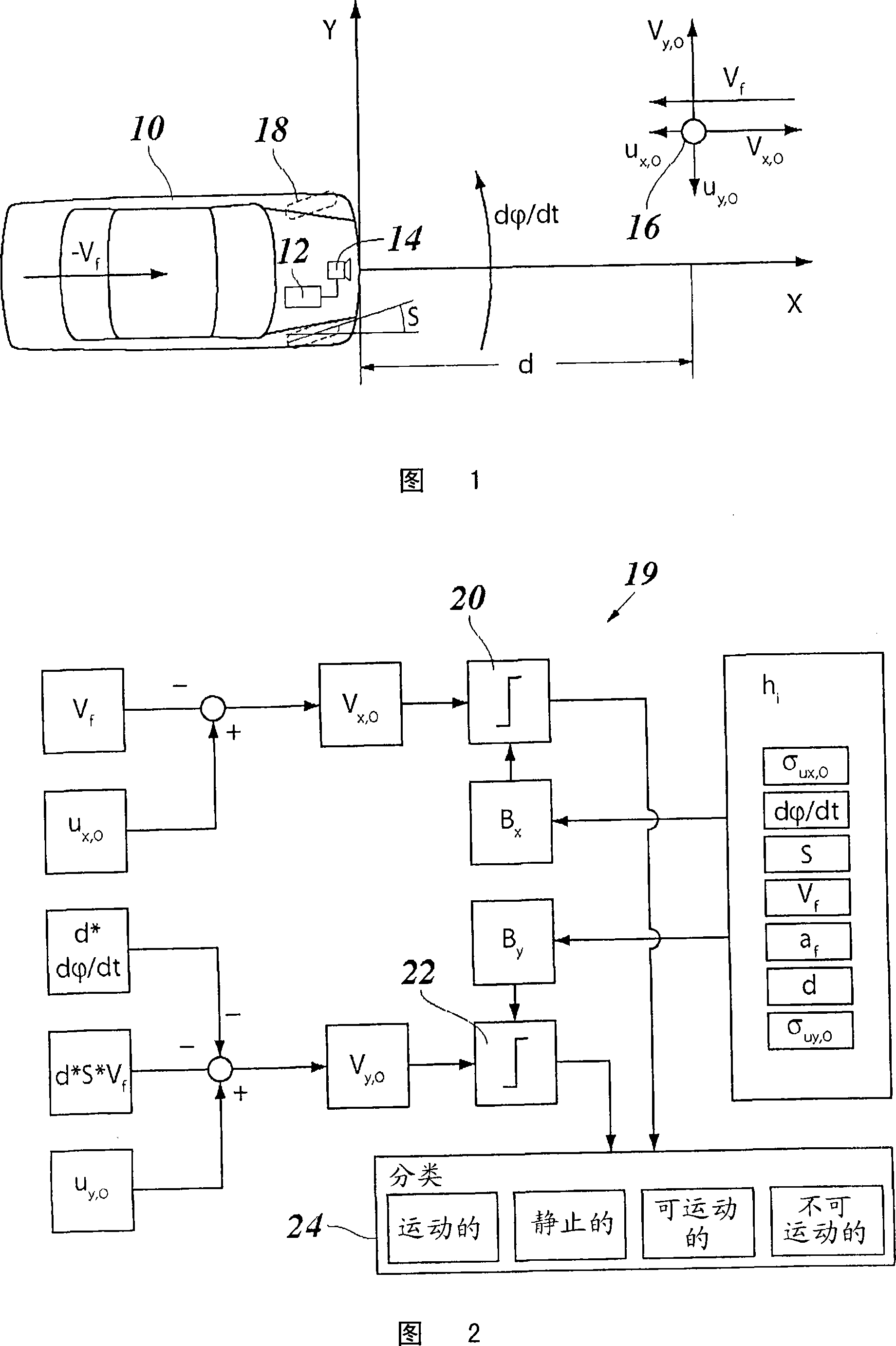
Figure 1 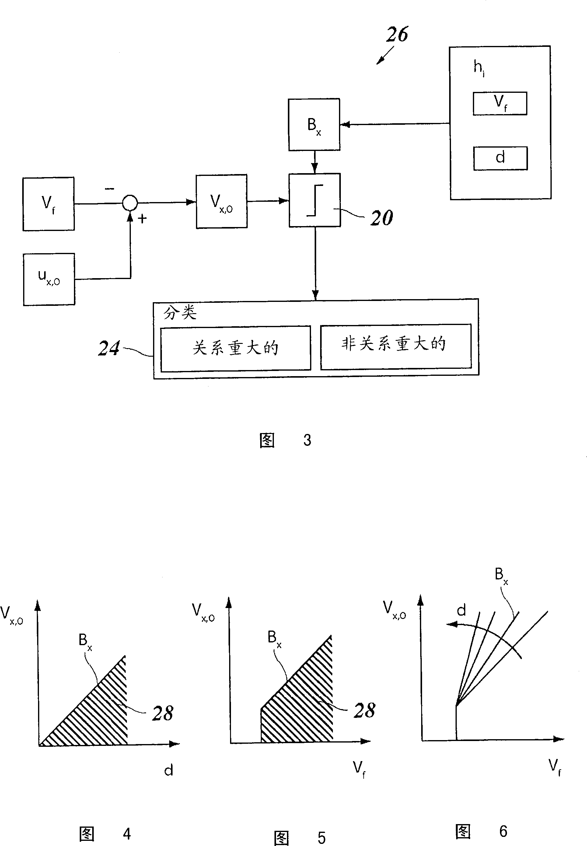
Figure 2
Abstract
Description
technical field
[0001] The invention relates to a driver assistance system for a motor vehicle with a localization system for locating an object in the surroundings of the motor vehicle and for comparing the relative movement of said object and the vehicle's own A means for comparing the difference between movements with a threshold. Background technique
[0002] Driver assistance systems are used to support the driver while driving the vehicle, warn him of imminent dangers and / or automatically take measures to mitigate the consequences of an encountered collision. For this purpose, the driver assistance system uses data from a localization system with which objects in the vehicle surroundings, in particular other road users, can be detected. Examples of such driver assistance systems are, for example, systems for lane departure warnings or ACC systems (adaptive cruise control systems), which are used for lane departure warnings when the driver is about to leave without fla...
Examples
Embodiment Construction
[0025] FIG. 1 shows a motor vehicle 10 which is equipped with a driver assistance system 12 such as an ACC system. A radar sensor 14 is installed as a positioning system. In the illustrated embodiment, there is a single target 16 within the localization range of the radar sensor, at which the distance d of the target in the X direction (the direction of travel of the automobile 10) and its distance d along the X direction can be directly measured. Relative velocity ux in direction, O. The radar sensor 12 has a certain angular resolution and can therefore also measure the azimuth angle at which the target 16 is viewed relative to the x-axis. The lateral position of the target in the Y-direction can thus be calculated using the measured distance d, and the relative velocity uy,O in the Y-direction can be calculated from the time derivative.
[0026]In FIG. 1 , a vector Vf is drawn above the target 16 , which vector Vf indicates the “own speed” of the vehicle 10 . More precise...