
Liquid crystal display device and manufacturing method thereof
A device and substrate technology, applied in the field of display devices, can solve problems such as decreased productivity and increased LCD manufacturing costs
Patent Information
- Authority / Receiving Office
- CN · China
- Patent Type
- Patents(China)
- Current Assignee / Owner
- Publication Date
- 2012-12-05
- Estimated Expiration
- Not applicable · inactive patent
Smart Images
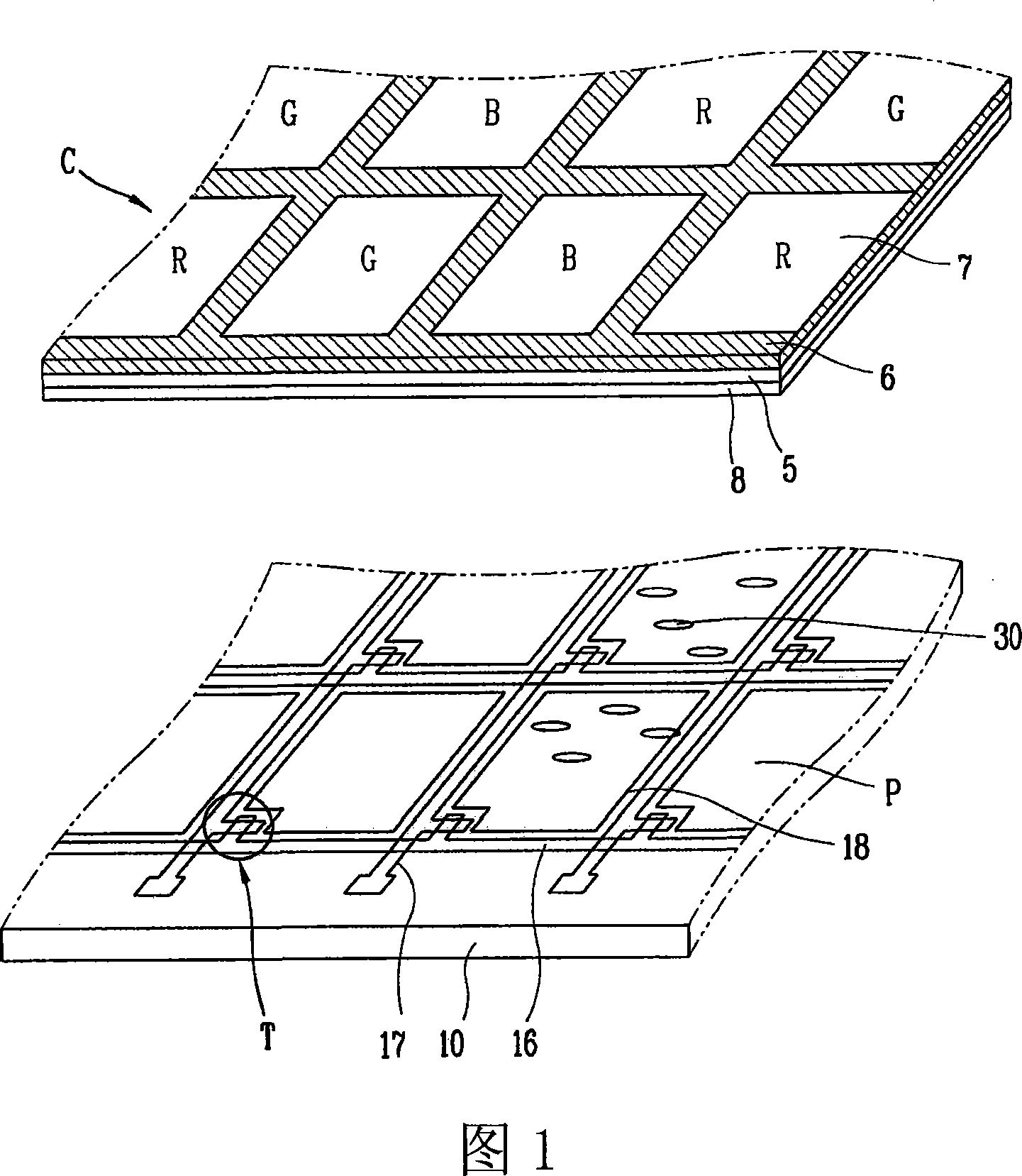
Figure 1 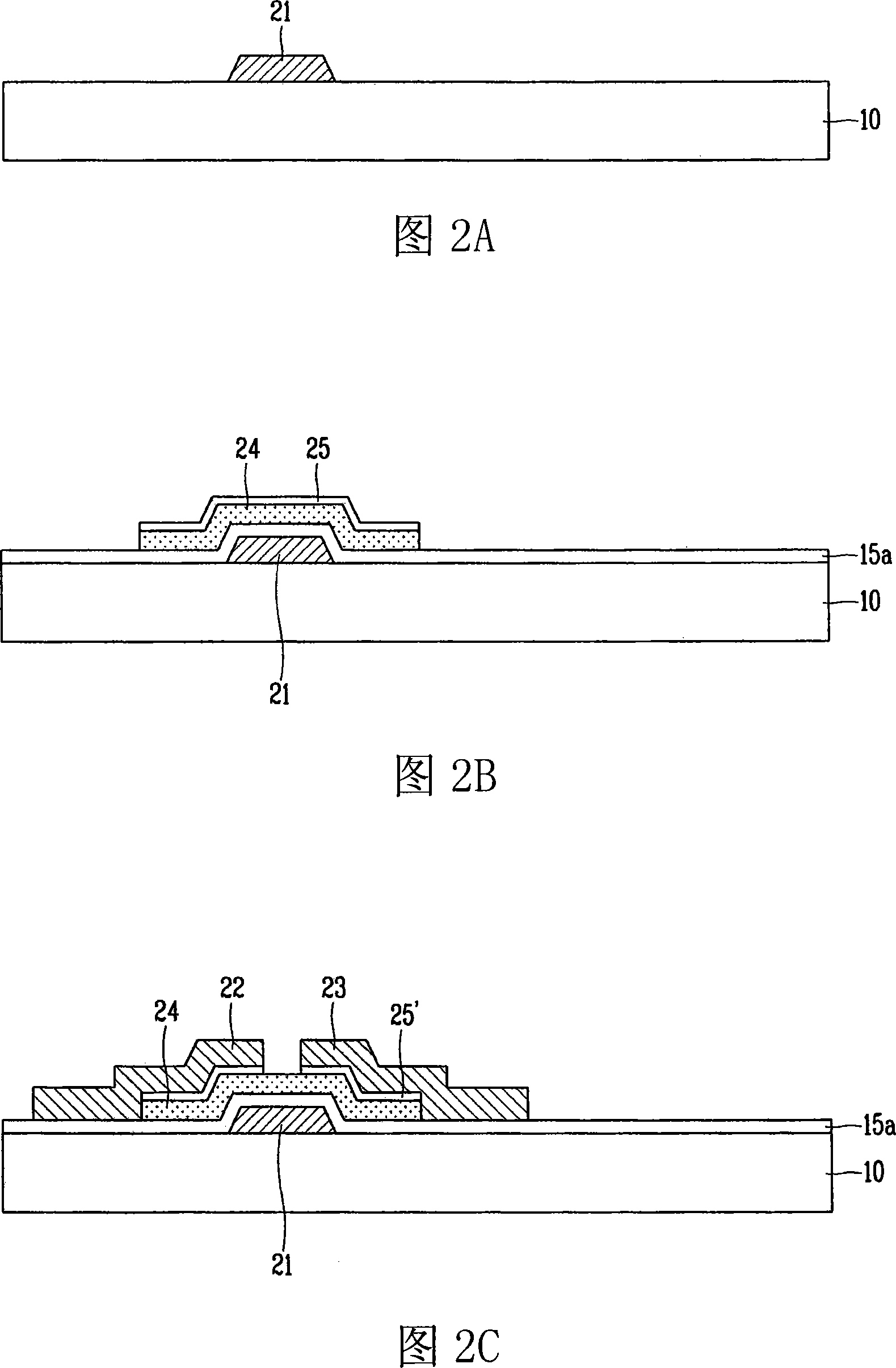
Figure 2 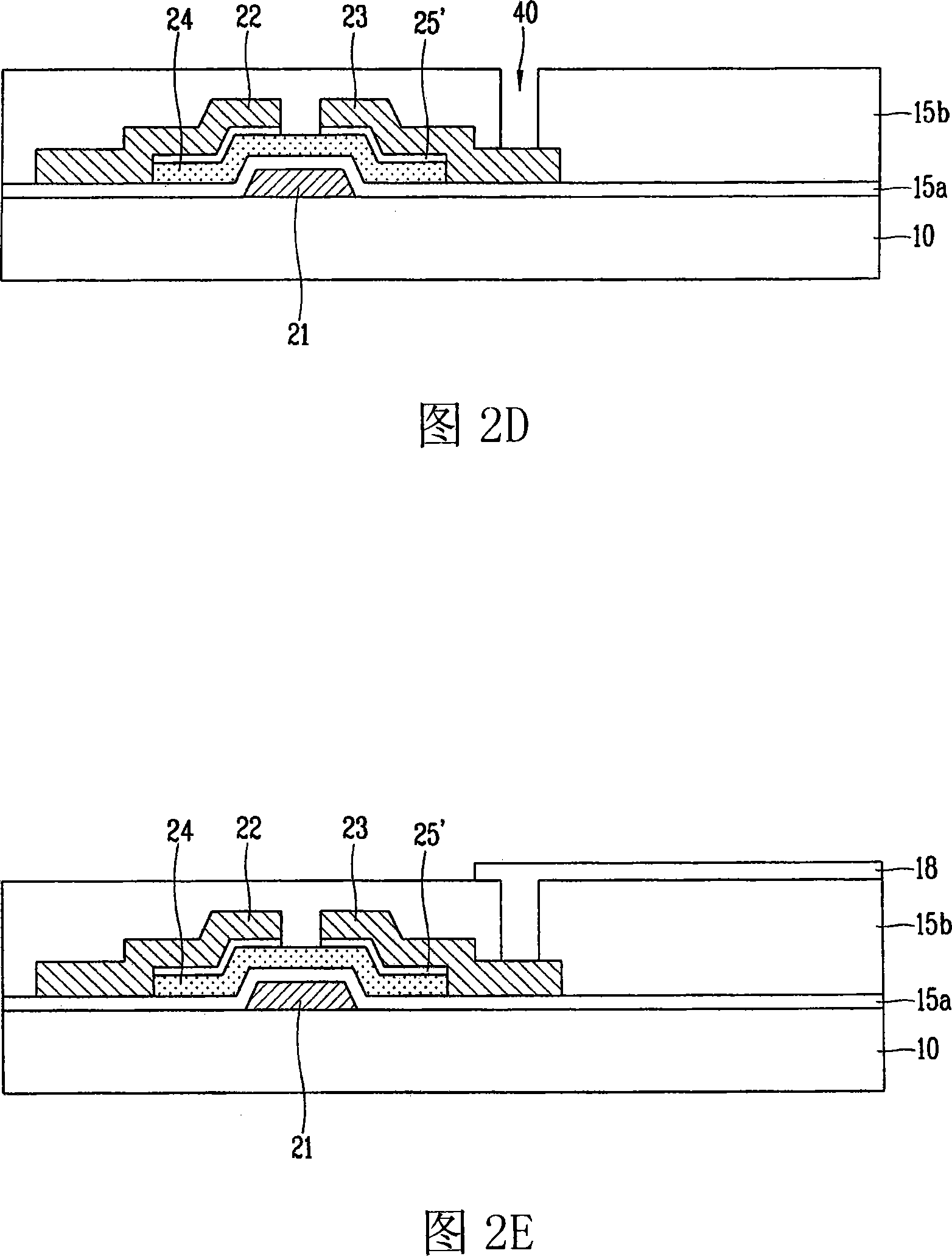
Figure 3
Abstract
Description
technical field
[0001] Embodiments of the present invention relate to a display device, in particular to a liquid crystal display (LCD) device and a manufacturing method thereof. Although the embodiments of the present invention are applicable to a wide range of applications, they are particularly suitable for simplifying the manufacturing process by reducing the number of masks, improving productivity, and improving device reliability. Background technique
[0002] As consumer interest in information displays increases and demand for portable (mobile) information devices increases, research and commercialization of light and thin flat panel displays ("FPDs") are also increasing.
[0003] Among FPDs, a liquid crystal display ("LCD") is a device for displaying images by using optical anisotropy of liquid crystals. The LCD device exhibits excellent resolution as well as color and image quality, so that it is widely used for notebook computers or desktop monitors, and the like...
Examples
Embodiment Construction
[0037] A liquid crystal display (LCD) and a method of manufacturing the same will now be described in detail with reference to the accompanying drawings.
[0038] image 3 Shown is a plan view of a part of an array substrate of an LCD according to a first embodiment of the present invention, in which a single pixel including a gate pad part and a data pad part is shown for convenience of explanation.
[0039] Actually, N gate lines and M data lines are formed to cross each other, thereby defining M×N pixels. To simplify explanation, only a single pixel is shown.
[0040] Such as image 3 As shown in , the gate lines 116 and the data lines 117 are formed to be arranged vertically and horizontally, thereby defining a pixel area on the array substrate 110 . A thin film transistor (TFT), that is, a switching element, is formed at an intersection of the gate line 116 and the data line 117 . A pixel electrode 118 is formed in the pixel area, which is connected to the TFT to driv...