
Decelerating casing of decelerating clutch of washing machine
A deceleration clutch and washing machine technology, applied in the field of washing machines, can solve the problems of high cost, low production efficiency, complex processing technology, etc., and achieve the effect of low cost, high production efficiency and simple processing technology
Patent Information
- Authority / Receiving Office
- CN · China
- Patent Type
- Applications(China)
- Current Assignee / Owner
- Publication Date
- 2008-12-31
- Estimated Expiration
- Not applicable · inactive patent
Smart Images
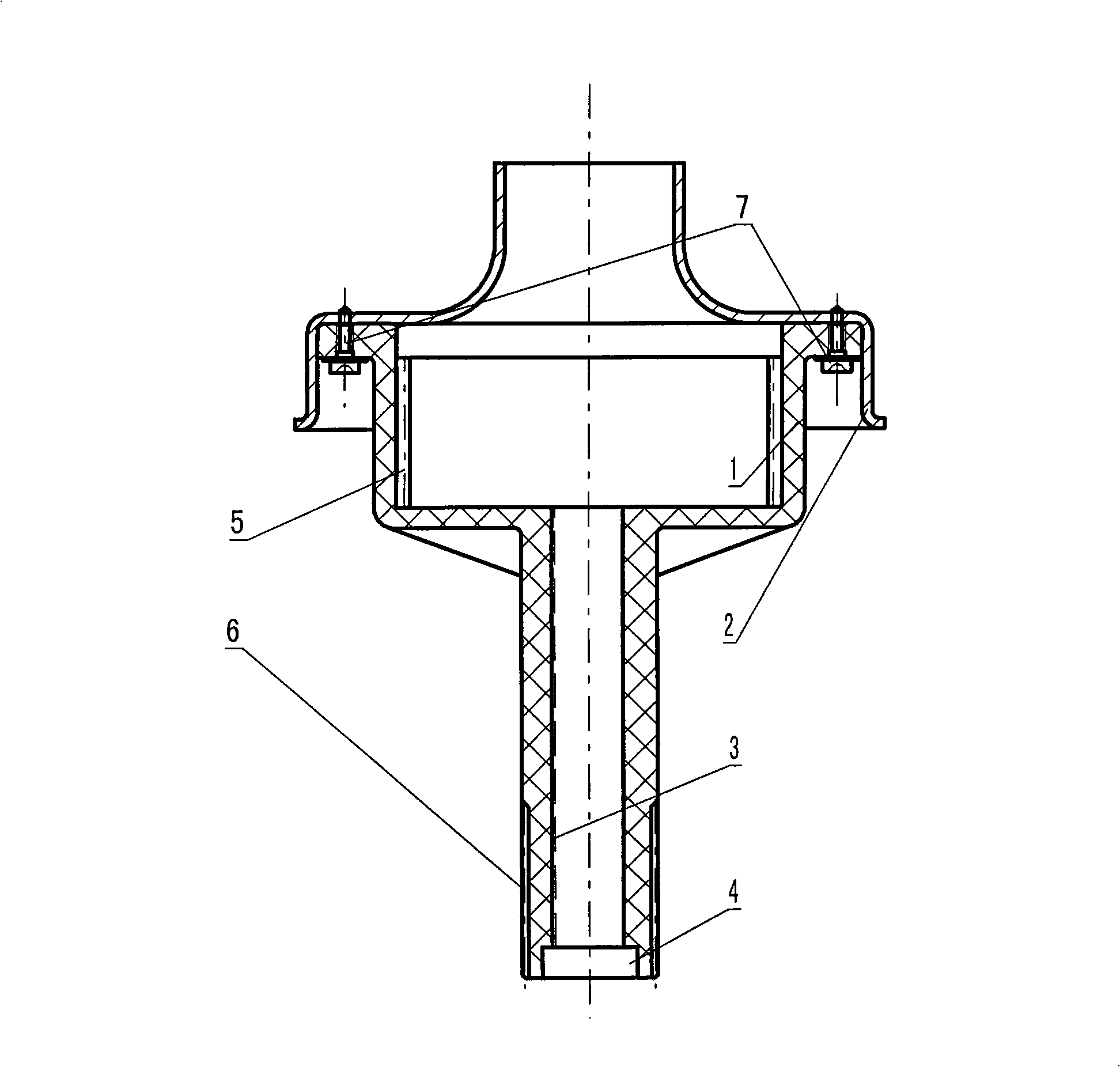
Figure 1
Abstract
Description
technical field
[0001] The technical solution of the invention relates to the technical field of washing machines, in particular to the manufacture of a deceleration clutch deceleration housing of a washing machine. Background technique
[0002] In the prior art, the deceleration housing of the deceleration clutch of the washing machine is composed of an input shaft sleeve and a brake wheel. In terms of technology, the input shaft sleeve is rolled and riveted on the brake wheel. In the installation of the gear train of the deceleration clutch of the washing machine, the gear train is located in the space formed by the input shaft sleeve rolling riveting on the brake wheel. In use, the input shaft passes through the input shaft sleeve, and transmits power to the gear train installed inside the brake wheel. Through the deceleration of the gear train, the power is transmitted to the output shaft installed inside the output shaft sleeve, so as to achieve the purpose of power out...
Examples
Embodiment Construction
[0019] Referring to FIG. 1 , a washing machine deceleration clutch deceleration housing is composed of an input shaft sleeve 1 and a brake disc 2 . The input shaft sleeve 1 is composed of two parts that are connected together, wherein the diameter of one part is larger than the other part, and the inside of the larger diameter part is a cavity that can accommodate the gear train, and the inner wall is provided with internal teeth 5; the diameter of the input shaft sleeve 1 is larger. The inner wall of the small part is provided with an oil guide groove 3, and the end is provided with an oil seal cavity 4; the outer wall of the input shaft sleeve 1 with a smaller diameter is provided with a spline 6; in terms of processing, it is best to use engineering plastic injection molding, or it can be Made of zinc and aluminum alloy. The brake disc 2 is a metal drawn part made of steel plate, which fits on the end of the larger diameter part of the input shaft sleeve, and the fastening ...