
Gas and gas appliance valve pressure relief device
A pressure relief device and valve technology, which is applied in the direction of preventing volumetric instrument damage, etc., can solve the problems of insufficient opening of the valve, failure to open the valve, and large power consumption, etc., and achieve the effects of fast pressure relief, stable work, and good sensitivity
Patent Information
- Authority / Receiving Office
- CN · China
- Patent Type
- Patents(China)
- Current Assignee / Owner
- Publication Date
- 2010-08-25
Smart Images
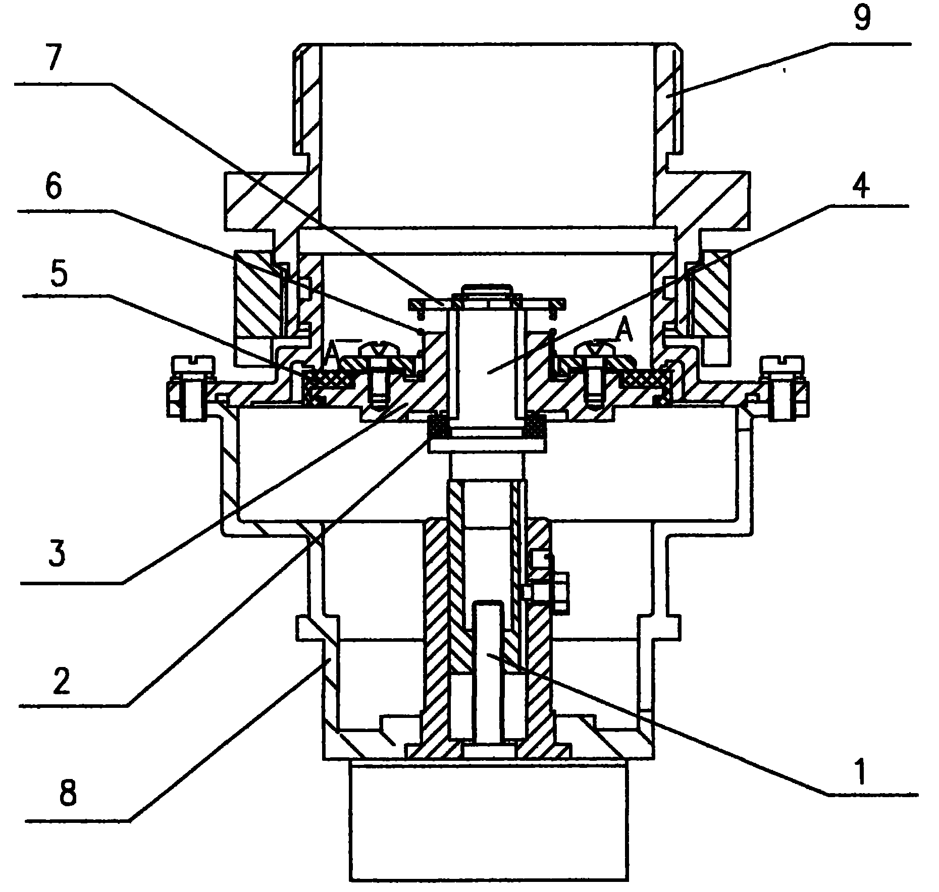
Figure 1 
Figure 2 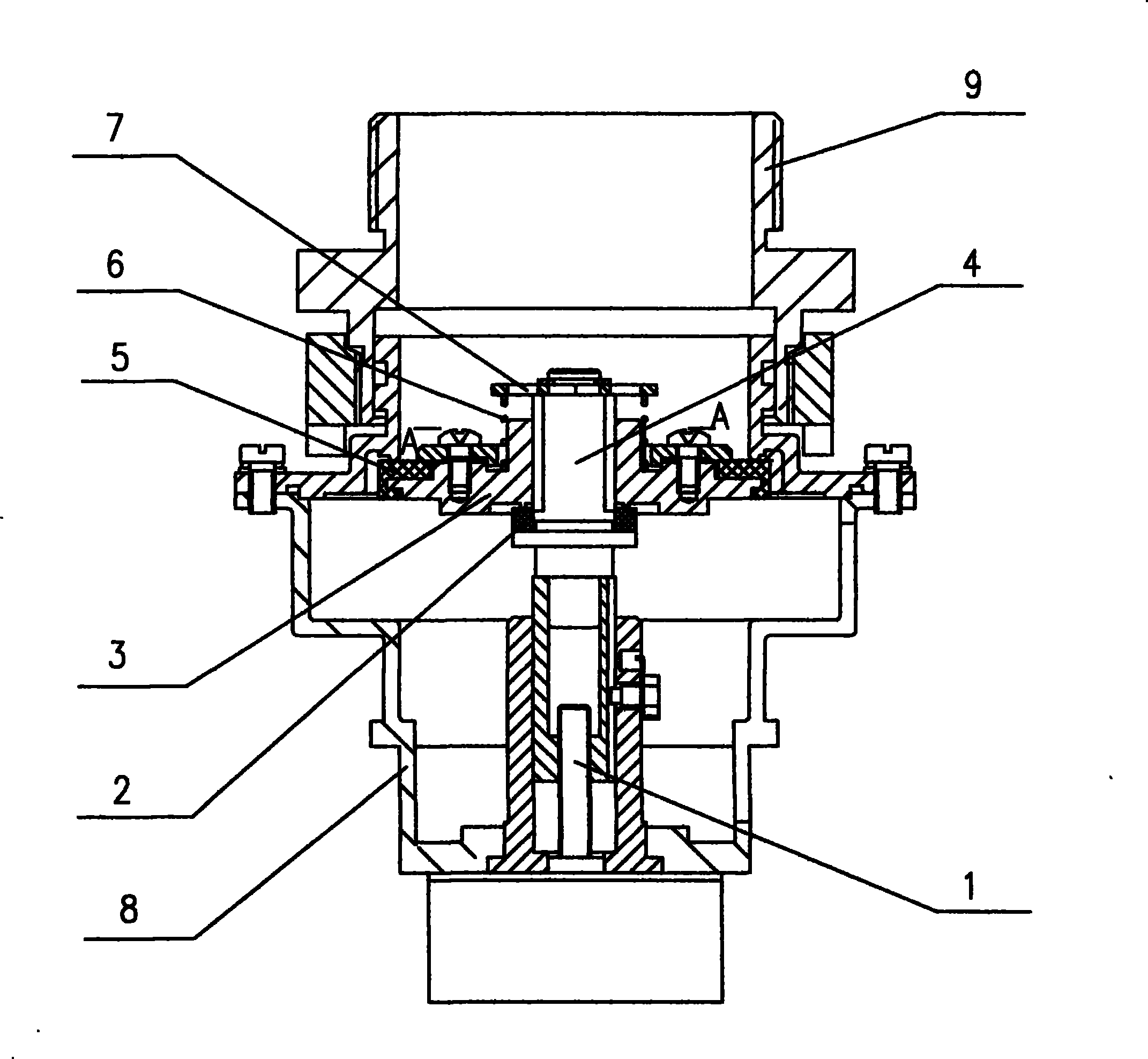
Figure 3
Abstract
Description
technical field
[0001] The invention relates to a metering instrument component device, in particular to a valve pressure relief device for gas and gas appliances. Background technique
[0002] Valve pressure relief device for gas and gas appliances, used at the gas outlet. Existing gas and gas appliance valves, as shown in Figure 1, in the valve closed state, the pressure of the intake chamber can reach 50kPa at most according to the national standard. The pressure head equipped with the rubber pad is subjected to a large internal pressure, and a large driving force is required when the battery-powered electric gas valve is opened. Often, the valve is not opened properly or even does not open within the designed valve opening time. The power consumption is large, and the driving power is generally two 3.6V lithium batteries and 3.0V~6.0V alkaline batteries, which are difficult to meet the design power requirements. Contents of the invention
[0003] Aiming at the defect...
Examples
Embodiment Construction
[0011] The structure of the present invention is illustrated in conjunction with the accompanying drawings.
[0012] A valve pressure relief device for gas and gas appliances, as shown in Figure 2, wherein the valve body, gas meter joint, and lead screw are the same as the existing pressure relief device, and a pressure relief valve with a pressure relief gap is installed in the valve body 8. body 4, the pressure relief body 4 is shaped on a missing surface, and the arcuate area is not less than 4% of the pressure relief body 4 cross-sectional area. Pressure relief rubber pad 2 is placed on the pressure relief body 4, the pressure relief rubber pad 2 is equipped with a tray 3, the tray 3 and the pressure relief body 4 are a dynamic fit gap, the air port plane of the tray 3 and the pressure relief glue on the pressure relief body 4 The gasket 2 forms a seal, and the three ventilation gaps of the pressure relief body 4 form a ventilation channel. The valve port rubber pad 5 on ...