
Calibration device for attitude indicator
The technology of a calibration device and an attitude meter is applied in the field of inspection of the performance of sea state measuring instruments, which can solve the problem of not knowing the correctness of the detection instruments, and achieve the effects of high accuracy, large adjustment range and small volume.
Patent Information
- Authority / Receiving Office
- CN · China
- Patent Type
- Patents(China)
- Current Assignee / Owner
- Publication Date
- 2014-04-02
- Estimated Expiration
- Not applicable · inactive patent
Smart Images
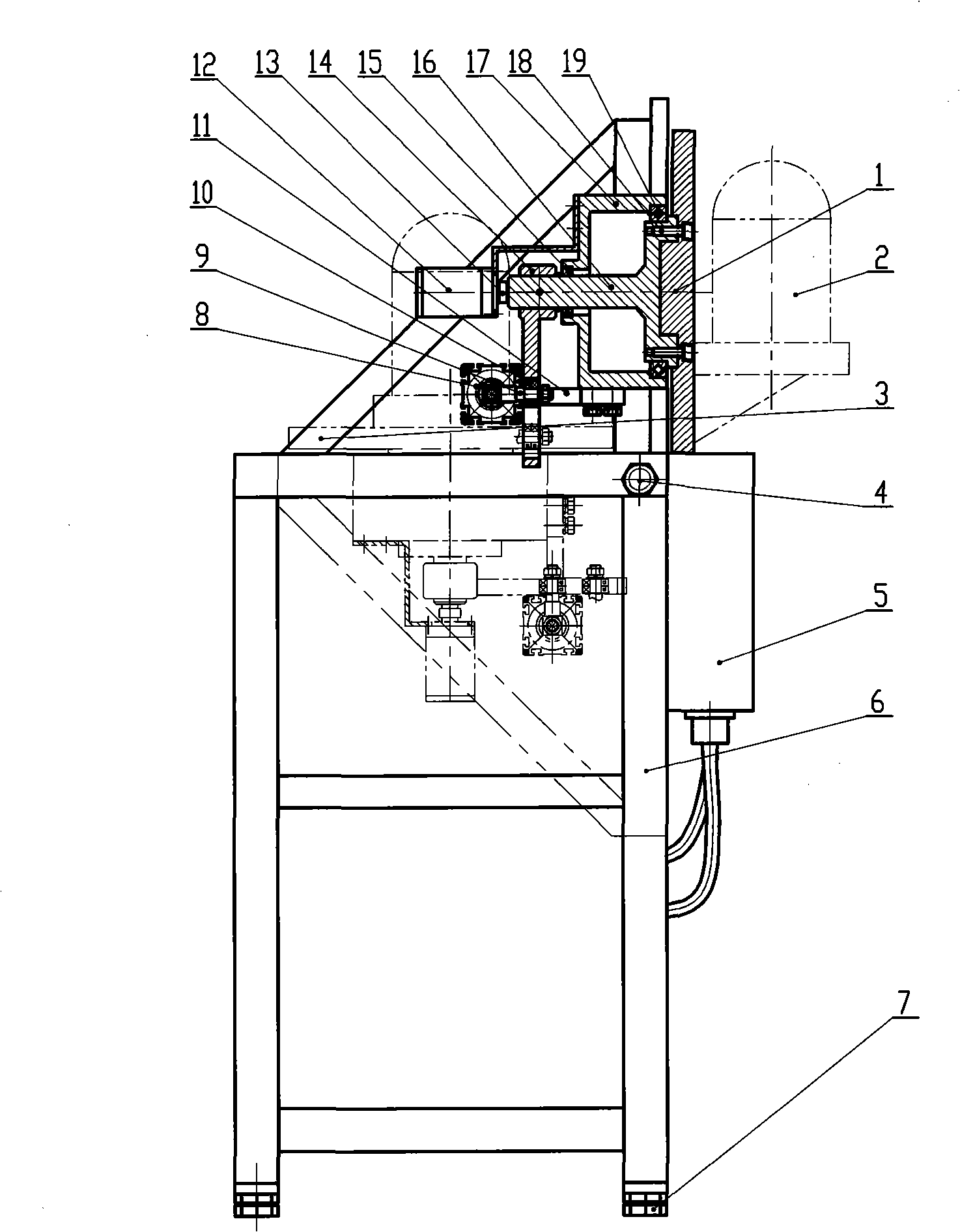
Figure 1 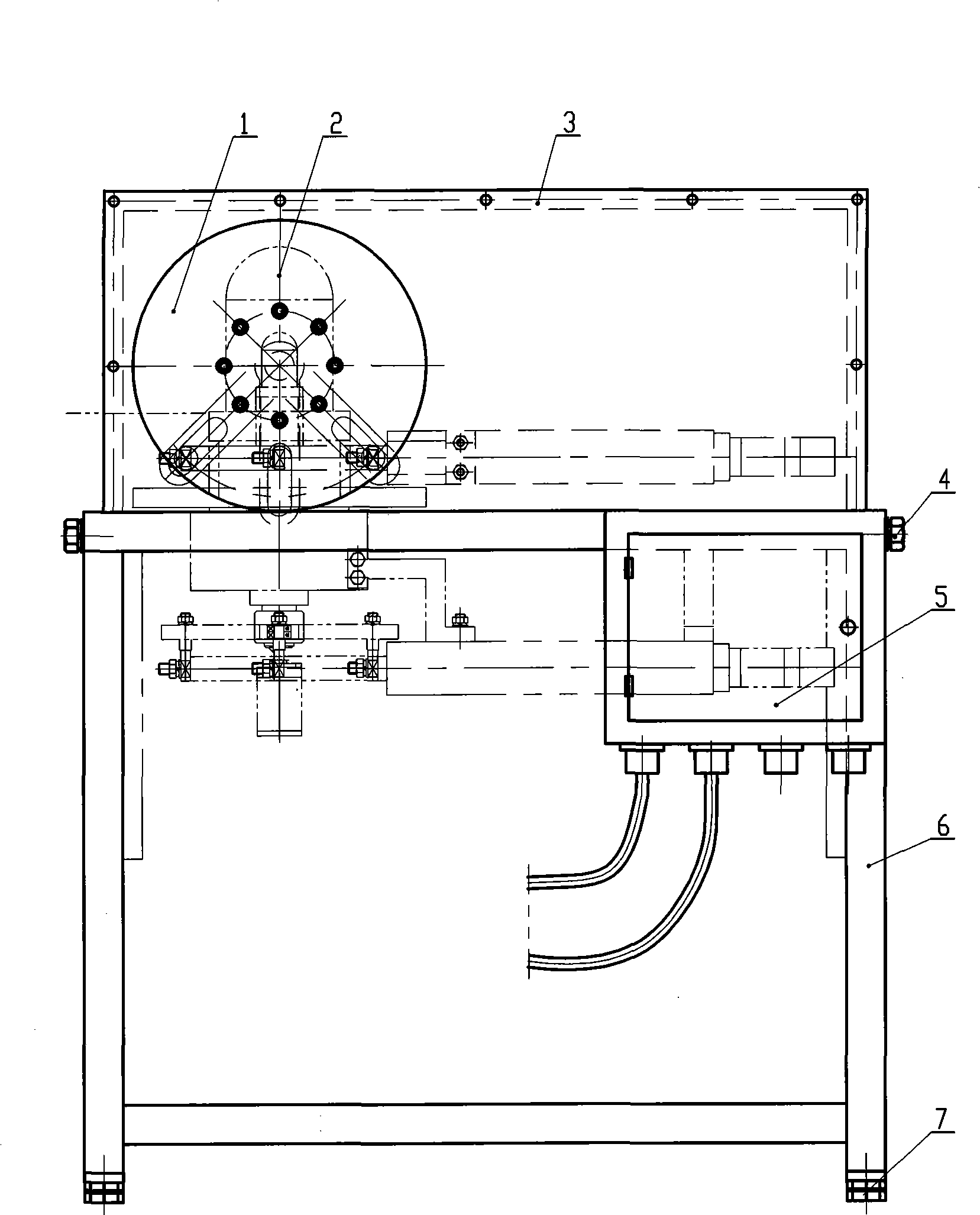
Figure 2 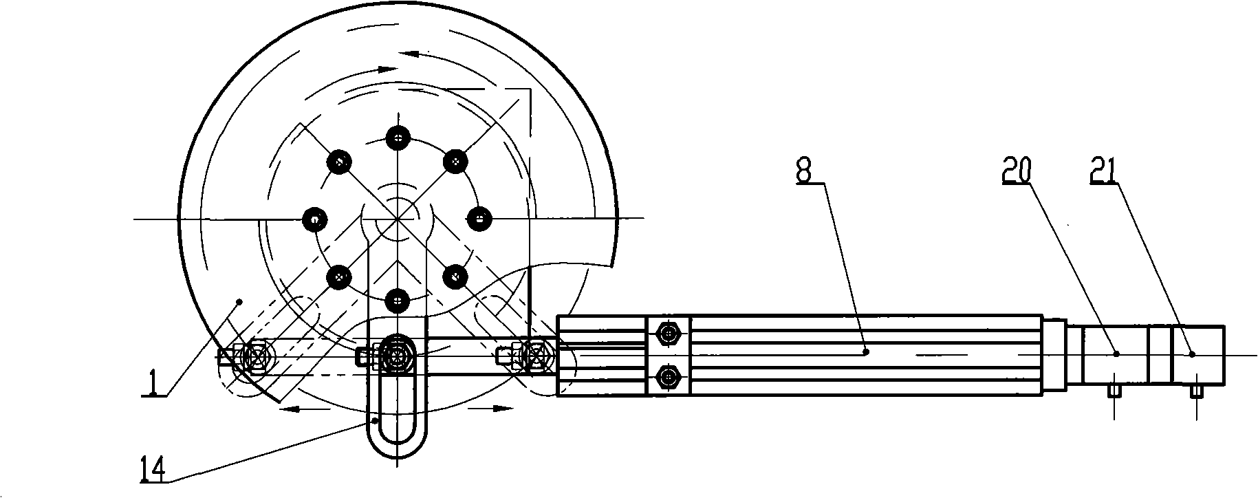
Figure 3
Abstract
Description
technical field
[0001] The invention relates to a ship model test, in particular to a performance test of a sea state measuring instrument. Background technique
[0002] The correctness of the sea state detection instrument has a direct impact on the correctness of the ship model performance test. The testing instrument is a non-standard equipment and has no centralized unit of measurement. I do not know the accuracy of the testing instrument during the previous use. In order to correctly identify the accuracy of the detection instrument, a set of calibration device is required to calibrate the sea state detection instrument to determine the correctness of the detection instrument.
[0003] In order to solve the above problems, the present invention provides a calibration device for calibrating the X, Y, and Z three-axis swing angles of the attitude instrument, which has good stability, convenient operation and high calibration accuracy. Contents of the invention [0004...
Examples
Embodiment Construction
[0017] The attitude instrument calibrating device of the present invention will be further described below in conjunction with the accompanying drawings and specific embodiments.
[0018] Such as figure 1 As shown, the attitude meter calibration device of the present invention includes a workbench 1, an attitude meter 2, a rotating bracket 3, a rotating mandrel 4, a control box 5, a stand 6, an adjusting screw 7, an intelligent combination unit (electric cylinder) 8, a connecting Shaft 9, bearing 10, bracket 11, angular displacement transmitter 12, coupling 13, connecting rod 14, rear bearing 15, rotating shaft 16, support 17, cross roller collar 18, screw 19, servo drive motor 20. Photoelectric encoder 21 and other components. The servo drive motor 20 and the photoelectric encoder 21 on the intelligent combination unit (electric cylinder) 8 of the posture rotating parts push the connecting rod 14 to swing through the coupling shaft 9 and the bearing 10, and drive the rotatin...