
Pressure relief apparatus of high voltage switch cabinet
A high-voltage switchgear and pressure relief device technology, applied in the direction of switchgear, switchgear settings, electrical components, etc., can solve the problems of unfavorable safe operation of switchgear, potential safety hazards of operators, and easy injury or damage to equipment. To achieve the effect of improving practical safety, ensuring safety in use, and ensuring safety
Patent Information
- Authority / Receiving Office
- CN · China
- Current Assignee / Owner
- Publication Date
- 2015-05-20
Smart Images
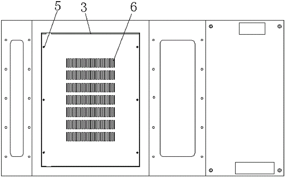
Figure 1 
Figure 2 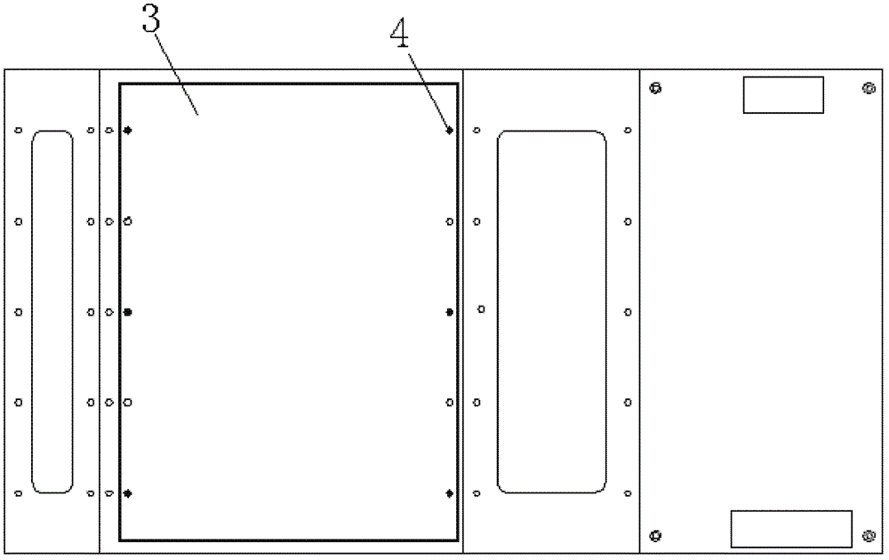
Figure 3
Abstract
Description
technical field
[0001] The invention relates to the field of electrical switches, in particular to a pressure relief device for a high-voltage switch cabinet. Background technique
[0002] In the current power system, the middle-mounted (KYN28-12) AC closed high-voltage switchgear, such as figure 2 , image 3 and Figure 4 As shown, including the cabinet body, a pressure relief cover is installed above the busbar chamber of the cabinet body, and the pressure relief cover is connected with the busbar chamber by plastic screws; the purpose is to prevent any short-circuit fault in the busbar chamber, resulting in a sharp increase in the internal pressure of the busbar chamber. , The pressure relief cover can be flushed open to achieve the purpose of pressure relief inside the cabinet and ensure the safe operation of the high-voltage switchgear. Although this kind of pressure relief device can reduce the pressure in the busbar room in case of failure and ensure the safety of ...
Examples
Embodiment Construction
[0026] The specific implementation manner of the present invention will be described in further detail below by describing the best embodiment with reference to the accompanying drawings.
[0027] Such as figure 1 and figure 2 As shown, the high-voltage switchgear pressure relief device includes a cabinet body 1, and a pressure relief cover 3 is provided above the busbar chamber 2 of the cabinet body 1. The pressure relief cover 3 and the busbar chamber 2 are connected by metal screws 5. The cover 3 is provided with a pressure relief hole 6 .
[0028] A wire mesh 7 is provided below the position where the pressure relief hole 6 is provided on the pressure relief cover 3, and the wire mesh 7 is welded on the pressure relief cover 6; the wire mesh 7 can strengthen the pressure relief at the place where the pressure relief hole 6 is provided The strength of the cover 3 prevents the position of the pressure relief cover 3 at the pressure relief hole 6 from being broken when the...