
Silicon chip taking and placing device
A pick-and-place device, silicon wafer technology, applied in transportation and packaging, conveyor objects, electrical components, etc., can solve problems such as affecting the production process of silicon wafers, to improve the production efficiency of silicon wafers, ensure smooth, and ensure the production of silicon wafers effect of the process
Patent Information
- Authority / Receiving Office
- CN · China
- Patent Type
- Patents(China)
- Current Assignee / Owner
- Publication Date
- 2013-10-16
Smart Images
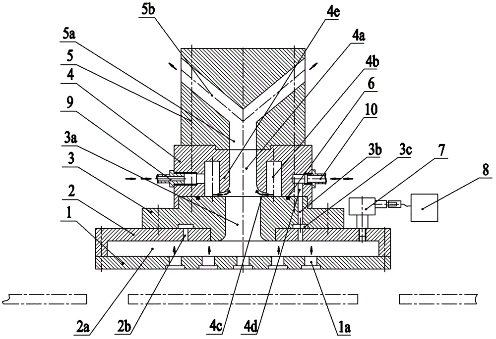
Figure 1 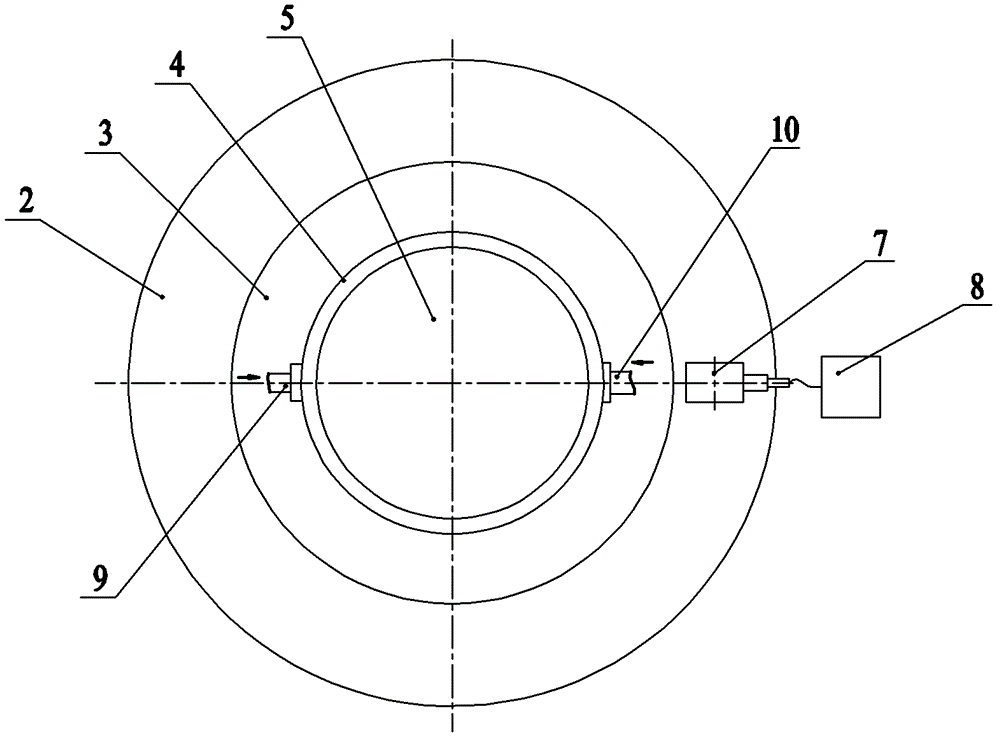
Figure 2 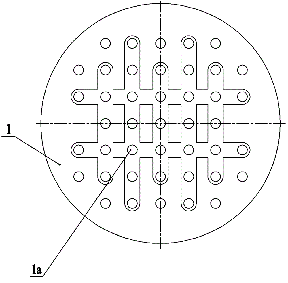
Figure 3
Abstract
Description
technical field
[0001] The invention belongs to the technical field of solar silicon wafer production, and in particular relates to a device for taking and placing silicon wafers during the production process of solar silicon wafers. Background technique
[0002] In the production process of solar silicon wafers, silicon wafers need to be transported on different conveying mechanisms. Most of the silicon wafer pick-and-place devices commonly used now are suction-type. The structure of the previous silicon wafer picking and placing device is as follows: Figure 4 As shown, it is mainly composed of a concave block 11, a sealing ring 12, a convex block 13, a joint 14 and a sensor 15, and the compressed air enters through the joint 14, and the compressed air passes through the gap between the concave block 11 and the convex block 13 to the surrounding at high speed. Discharging, so that a local vacuum negative pressure is generated directly under the bump 13, thereby sucking th...
Examples
Embodiment Construction
[0019] The present invention will be further described below in conjunction with specific drawings and embodiments.
[0020] As shown in the figure: the silicon chip pick-and-place device of the present invention is mainly composed of a suction cup 1, a connecting seat 2, a lower end cover 3, a valve body 4, an upper end cover 5, a sealing ring 6, a negative pressure sensor 7, a display 8, a first Parts such as joint 9 and second joint 10 are formed.
[0021] Such as Figure 1~Figure 3 As shown, the suction cup 1 is fixed on the connection base 2 by screws, the suction cup 1 is provided with a plurality of air holes 1a, and the connection base 2 is provided with a cavity 2a. The lower end cover 3 is fixed on the connection base 2 by screws, and the center of the lower end cover 3 is provided with a lower ventilation hole 3a, which communicates with the concave cavity 2a in the connection base 2. The valve body 4 is fixed on the lower end cover 3 by screws, and a sealing ring...