
Laminated floor slab for steel buildings
A technology for laminated floors and buildings, applied to floors, buildings, building components, etc., can solve problems such as short construction period, long construction period, and difficult hoisting, so as to improve crack resistance and earthquake resistance, excellent earthquake resistance, Guarantee the effect of pouring quality
Patent Information
- Authority / Receiving Office
- CN · China
- Patent Type
- Patents(China)
- Current Assignee / Owner
- Publication Date
- 2014-02-19
- Estimated Expiration
- Not applicable · inactive patent
Smart Images
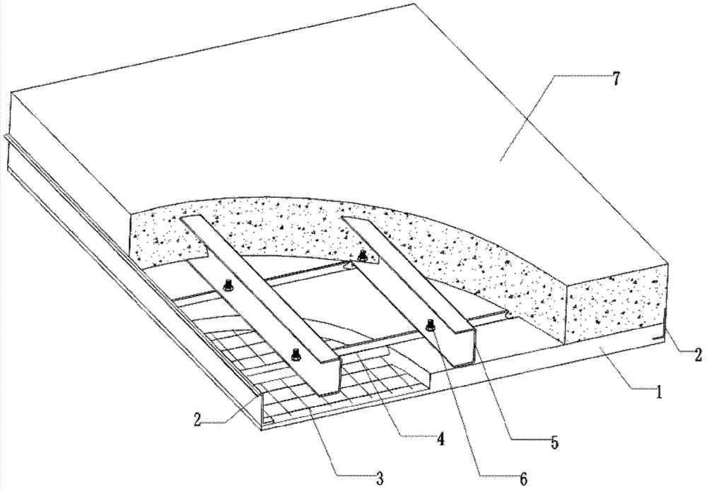
Figure 1 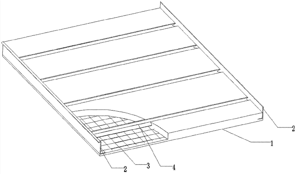
Figure 2 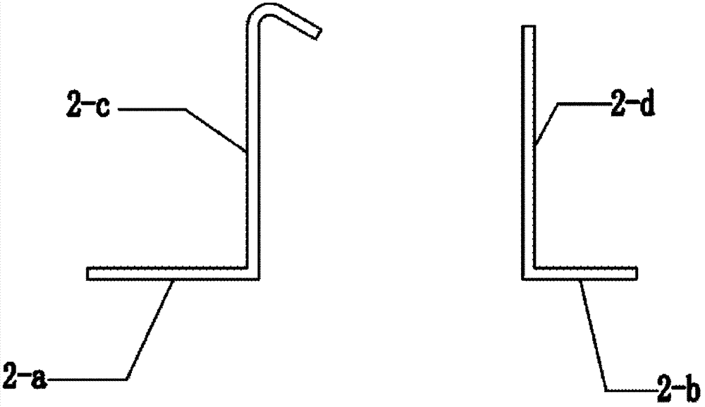
Figure 3
Abstract
Description
technical field
[0001] The invention relates to a laminated floor slab for a steel structure building, which belongs to the field of building profiles. Background technique
[0002] At present, there are cast-in-place floor slabs and prefabricated floor slabs used in China. The cast-in-place floor slabs have good integrity, but they need on-site formwork and concrete pouring. The construction period is long, difficult, and the formwork is worn out. The cost is high, and the prefabricated floor does not require on-site formwork, the construction period is short, and the cost is low, but the prefabricated components are self-heavy, difficult to hoist, cracks are prone to occur in the assembly parts of the components, and the integrity is poor. There are also deficiencies in the existing laminated floor slabs. Ribbed prestressed concrete prefabricated component slabs, including reinforced concrete bottom slab, reinforced concrete longitudinal ribs and bottom prestressed tendons...
Examples
Embodiment Construction
[0017] Below in conjunction with accompanying drawing, the present invention will be further described:
[0018] Prefabricated concrete floor 1: a pair of side plates 2a, 2b are arranged vertically, and the right-angled plates at the bottom are opposite to each other. One side plate 2a has an outer hook edge 2c on the upper edge, and the other side plate 2b has a straight line edge 2d on the upper edge. Such as image 3 As shown, the steel wire mesh 3 is laid between the two side plates 2a, 2b, placed on the right-angled plate surface at the bottom, and connected by self-tapping screws. On the wire mesh 3, connect each other with self-tapping screws, and then cast concrete 1a to form a concrete prefabricated floor 1, see figure 2 , and then place the middle keel 5 longitudinally on the horizontal groove steel belt 4, and connect and fix it with hexagonal bolts 6, such as Figure 4 , 5 , 6 shown. According to the design requirements, the keel 5 can be made of C-shaped stee...