
Additional air chamber of volume-variable air spring
A technology of additional air chamber and air spring, applied in the direction of gas shock absorber, can solve the problem that the volume of the additional air chamber cannot be changed, and achieve the effect of simple structure, low production process requirements, and guaranteed height
Patent Information
- Authority / Receiving Office
- CN · China
- Patent Type
- Patents(China)
- Current Assignee / Owner
- Publication Date
- 2014-02-12
- Estimated Expiration
- Not applicable · inactive patent
Smart Images
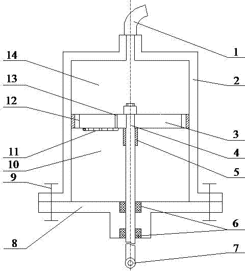
Figure 1 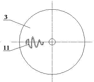
Figure 2 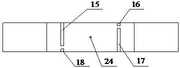
Figure 3
Abstract
Description
technical field
[0001] The invention relates to an additional air chamber of a vehicle air spring, in particular to an air spring additional air chamber with variable volume. Background technique
[0002] The air spring uses the compressibility of the gas to realize its elastic effect, and has the functions of cushioning and vibration isolation. The volume of the air spring has a significant impact on its stiffness characteristics. Zhu Sihong of Nanjing Agricultural University in China mentioned in his paper "Mechanical Characteristic Parameter Test of Air Spring with Additional Air Chamber" that as the volume of the additional air chamber of the air spring increases, The air spring stiffness becomes smaller.
[0003] In order to adapt the air suspension to various complex working conditions of the vehicle, the stiffness characteristics of the spring can be changed by changing the volume of the air spring, so that the advantages of the air spring can be fully exerted and th...
Examples
Embodiment Construction
[0021] Embodiments of the present invention will be described in detail below with reference to the accompanying drawings.
[0022] Such as figure 1 Shown is a variable-volume air spring additional air chamber for passenger cars, including an additional air chamber cavity 2 and a connecting pipeline 1, the closed end of the additional air chamber cavity 2 is connected to the air spring body through the connecting pipeline 1, and is open The ends are sealed by a cover plate 8. The piston 3 is installed in the cavity 2 of the additional air chamber, and the thickness of the piston is 25 mm. The piston rod 4 is assembled on the piston 3. The surface of the piston 3 near the cover plate 8 is equipped with a slender pipeline 11, and the slender pipeline 11 is wound into a "snake". Shape is fixed on the surface of piston 3. Such as figure 2 As shown, the slender pipeline 11 has a length of 350 mm, an inner diameter of 2 mm, and is bent 7 times. The length of each fold is 40 mm, ...