
Highly-efficient light emitting diode (LED) power supply
A technology of LED power supply and LED light source, applied in electric light source, light source, electric lamp circuit layout and other directions, can solve the problems of high power supply cost, increase hidden trouble of failure, and high cost, increase LED temperature compensation function, reduce production cost and failure rate , The effect of reducing the temperature of the working environment
Patent Information
- Authority / Receiving Office
- CN · China
- Patent Type
- Applications(China)
- Current Assignee / Owner
- Publication Date
- 2012-09-12
- Estimated Expiration
- Not applicable · inactive patent
Smart Images
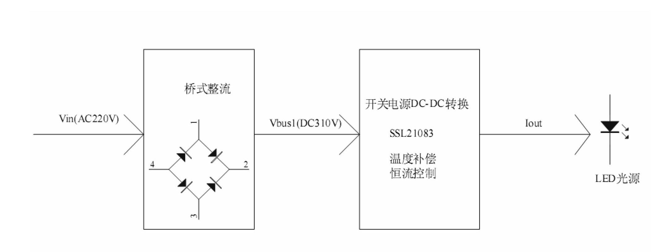
Figure 1 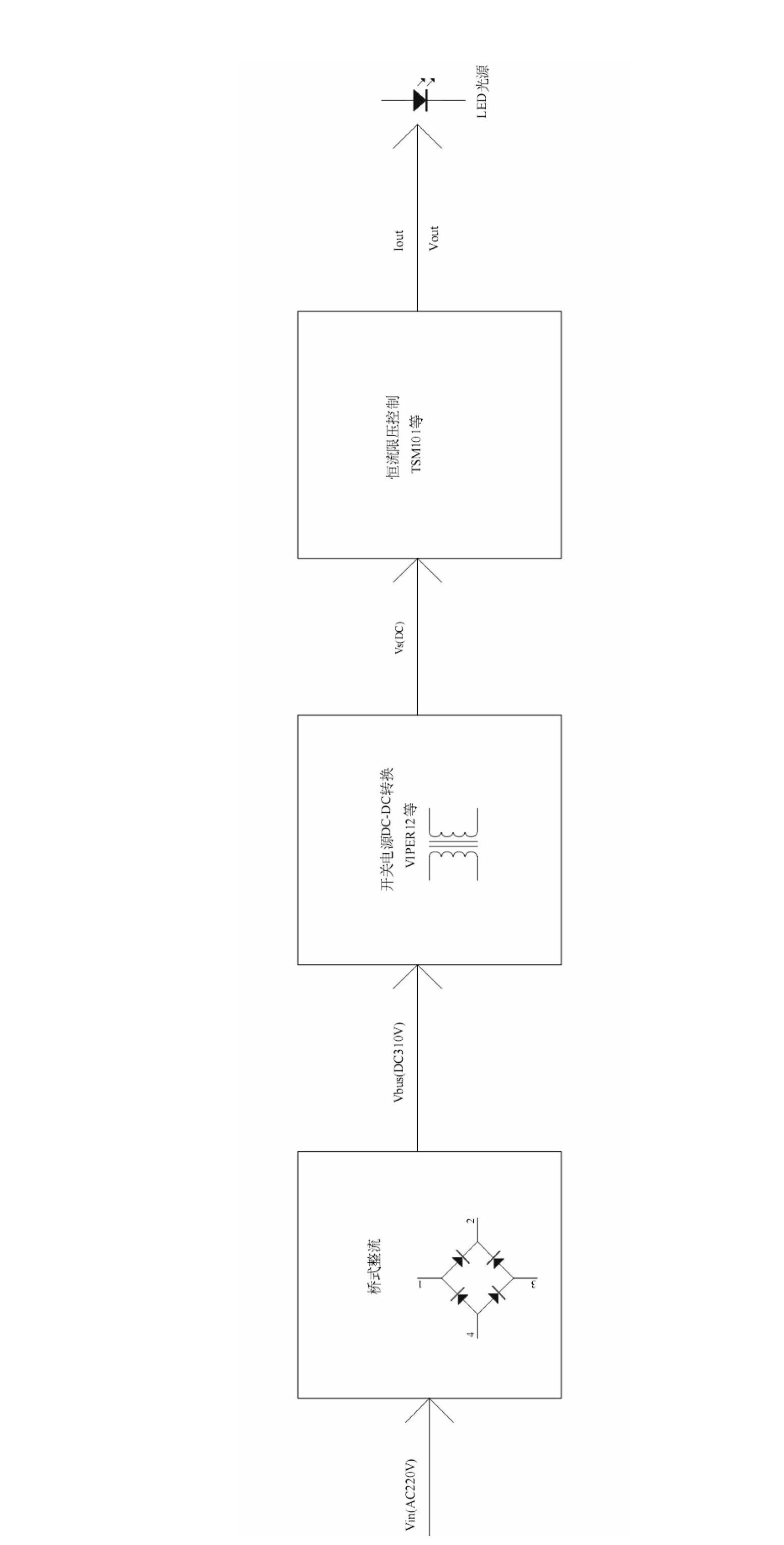
Figure 2 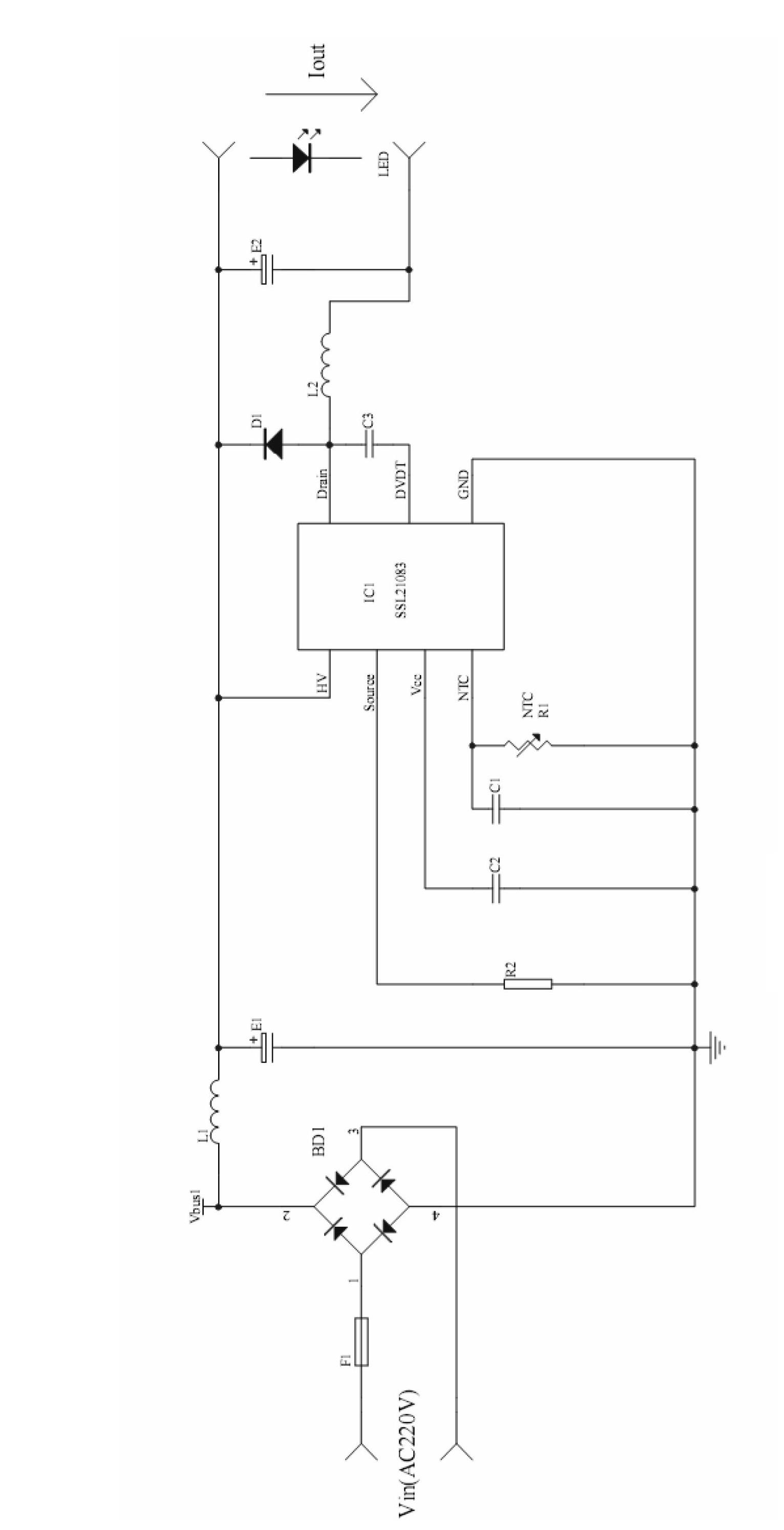
Figure 3
Abstract
Description
technical field
[0001] The invention relates to a power supply circuit, in particular to a high-efficiency LED power supply. Background technique
[0002] As a new lighting method, LED has the advantages of long life, low energy consumption, no mercury pollution, flexible application, etc., and has broad development prospects. Most of the current LED power supplies use a constant current output control scheme, which requires an isolation transformer.
[0003] Such as figure 1 As shown, the existing constant current output control scheme first rectifies the AC input into Vbus1, and then converts the high-voltage DC Vbus1 into the required low-voltage DC Vs through a transformer through a traditional DC-DC switching power supply circuit, such as VIPER12. Vs then passes through a constant current circuit such as TSM101 to obtain the Vout required by the load.
[0004] The most important problem that existing circuit exists is:
[0005] 1. Low efficiency and large volume. T...
Examples
Embodiment Construction
[0021] The present invention will be further described below in conjunction with drawings and embodiments. The present invention is used for LED lighting with AC 220V input and constant current output, including a bridge rectifier module and a switching power supply DC-DC conversion module. The output end of the bridge rectification module is connected to the LED light source through the switching power supply DC-DC conversion module, such as figure 2 shown. Specific circuit such as image 3 shown, including:
[0022] 1. Bridge rectifier module. Used to convert AC input into DC voltage Vbus1.
[0023] 2. Switching power supply conversion chip SSL21083 and peripheral circuits.
[0024] Such as image 3 , The power supply is a step-down BUCK circuit.
[0025] The rectifier bridge BD1 of the bridge rectifier module converts the AC input into a DC voltage Vbus1, and the waveform of Vbus1 is in the form of a half sine wave. The positive pole of the rectifier bridge BD1 is c...