
Powered below-knee prosthesis
A power and prosthetic technology, applied in the fields of prosthesis, medical science, artificial legs, etc., can solve the problems of unnatural walking speed, stiffness of the forefoot and heel, and easy fatigue of amputees, so as to meet the needs of deformation and good energy storage. and shock absorption, light weight effect
Patent Information
- Authority / Receiving Office
- CN · China
- Patent Type
- Applications(China)
- Current Assignee / Owner
- Publication Date
- 2013-01-16
Smart Images
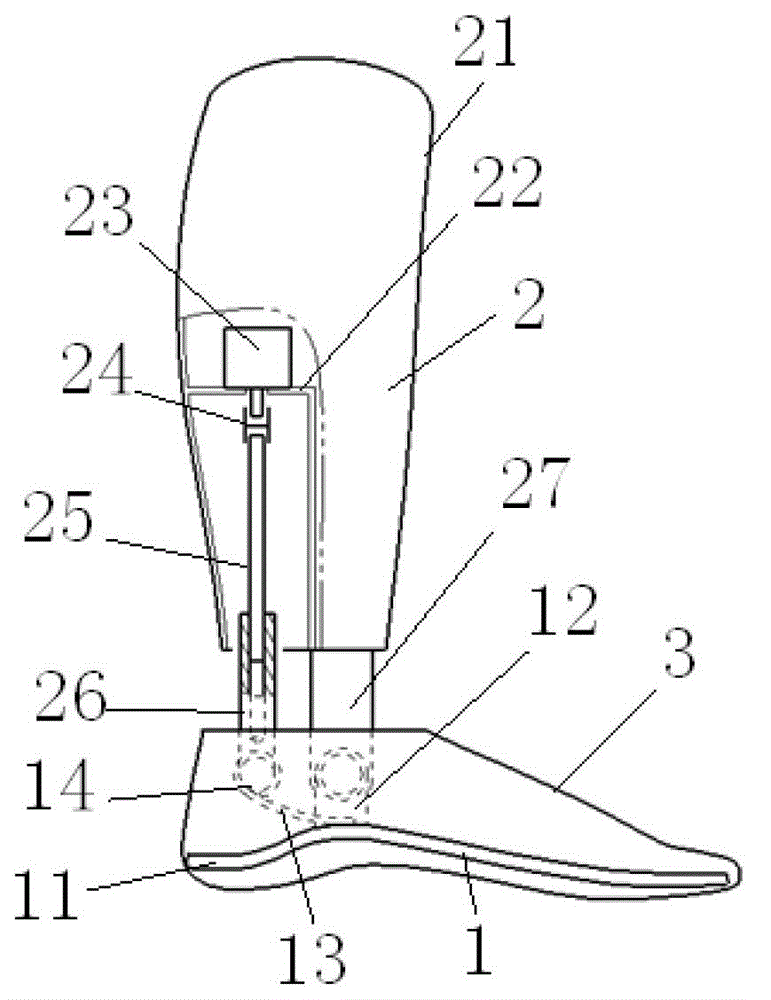
Figure 1 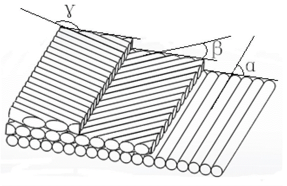
Figure 2
Abstract
Description
technical field
[0001] The invention relates to a human prosthesis, in particular to a dynamic under-knee prosthesis combining active and passive movement modes. Background technique
[0002] Below-the-knee prostheses currently in use are mainly divided into passive prostheses and active prostheses. The ankle joints of passive prostheses use single-axis ankles or universal ankle joints. The existing problem is that the walking speed cannot follow the amputee's walking speed naturally and freely. And changes, patients are often forced to lean forward to make up for the lack of propulsion ability, making amputee more likely to feel fatigue; active prosthetics are driven by motors, which can provide enough energy for the body to move forward, so as to realize the natural gait of the human body, but At present, the design of active prostheses about the ankle joint is relatively simple, which cannot well meet the needs of users. In addition, most of the prosthetic feet currently...
Examples
Embodiment Construction
[0013] The present invention will be described in detail below in conjunction with the accompanying drawings and embodiments.
[0014] like figure 1 As shown, the present invention includes a prosthetic foot 1 and a calf prosthesis 2, and may also include a foot cover 3 wrapped outside the prosthetic foot 1.
[0015] The prosthetic foot plate 1 of the present invention comprises a foot plate 11, the middle part of the foot plate 11 has a higher arch, and a seat 12 is fixedly arranged on the top surface of the foot plate 11 at the arched part. The rear portion of the foot plate 11 is provided with an upwardly curved elastic connecting rod 13, the front portion of the elastic connecting rod 13 is fixedly connected to the top of the arched part of the foot plate 11, and an elastic movable space is arranged between the rear portion of the elastic connecting rod 13 and the foot plate 11. And another support 14 is fixedly arranged on the top of the rear end of the elastic connectin...