
Passive visual sensor based on weld automatic tracking of welding robot
A visual sensor and welding robot technology, applied in welding equipment, welding accessories, arc welding equipment, etc., can solve the problems of unfavorable small-angle weld welding, large sensor volume and weight, unfavorable welding, etc., to facilitate installation and maintenance, The effect of great flexibility and expandability, and easy operation
Patent Information
- Authority / Receiving Office
- CN · China
- Patent Type
- Patents(China)
- Current Assignee / Owner
- Publication Date
- 2012-11-28
- Estimated Expiration
- Not applicable · inactive patent
Smart Images
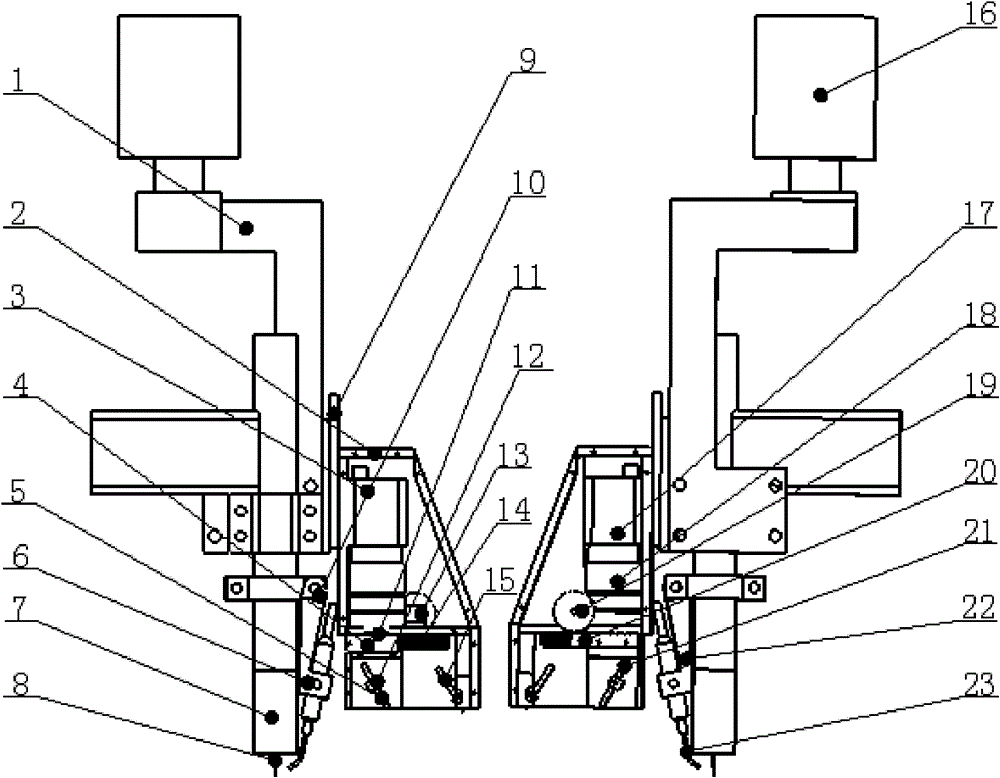
Figure 1
Abstract
Description
technical field
[0001] The invention relates to a device in the technical field of robot welding, in particular to a passive vision sensor based on a welding robot GTAW (argon tungsten arc welding) welding seam autonomous tracking. Background technique
[0002] Robotic welding quality control has always been a hot and difficult point in welding research, and it is also an important topic for welding workers to study. In actual welding, there are often factors such as deformation, variable heat dissipation, variable gap, and variable edge, which affect the quality of weld formation. In order to overcome the influence of these uncertain factors in the welding process on the quality of precision welded parts, it is urgent to use information feedback, intelligent control and other technologies to improve the adaptability or intelligence level of the current welding robot, and realize the intelligent control of the robot welding process. In order to realize intelligent and accur...
Examples
Embodiment Construction
[0019] The embodiments of the present invention are described in detail below. This embodiment is implemented on the premise of the technical solution of the present invention, and detailed implementation methods and specific operating procedures are provided, but the protection scope of the present invention is not limited to the following implementation example.
[0020] Such as figure 1 As shown, this embodiment includes: a mounting bracket 1, a system housing 2, a camera 3, a light reduction filter system 4, a light reflection system 5 and a wire feeding adjustment mechanism 6, wherein: the camera 3 and the light reduction filter system 4 are welded During the process, it is coaxially set on the inner wall of the system shell 2 and transmits the image information of the weld seam during the welding process. The light reduction filter system 4 is driven by the motor transmission system during the non-welding process and realizes the guidance and calibration before welding. ...