
Precious metal jewelry burnishing robot
A robot and precious metal technology, applied in manipulators, program-controlled manipulators, chucks, etc., can solve the problems of low calendering efficiency, operators are susceptible to strain and pain, and achieve the effect of reducing personnel loss and improving calendering efficiency.
Patent Information
- Authority / Receiving Office
- CN · China
- Current Assignee / Owner
- Publication Date
- 2013-08-14
- Estimated Expiration
- Not applicable · inactive patent
Smart Images
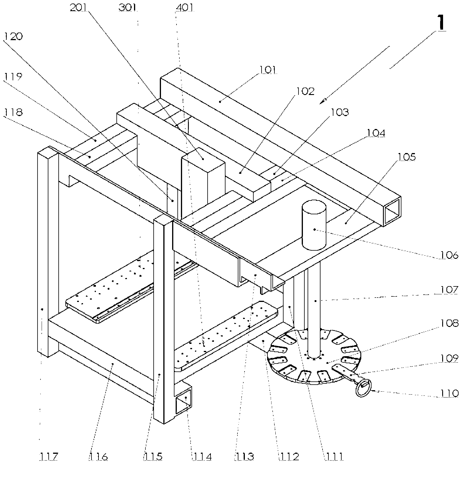
Figure 1 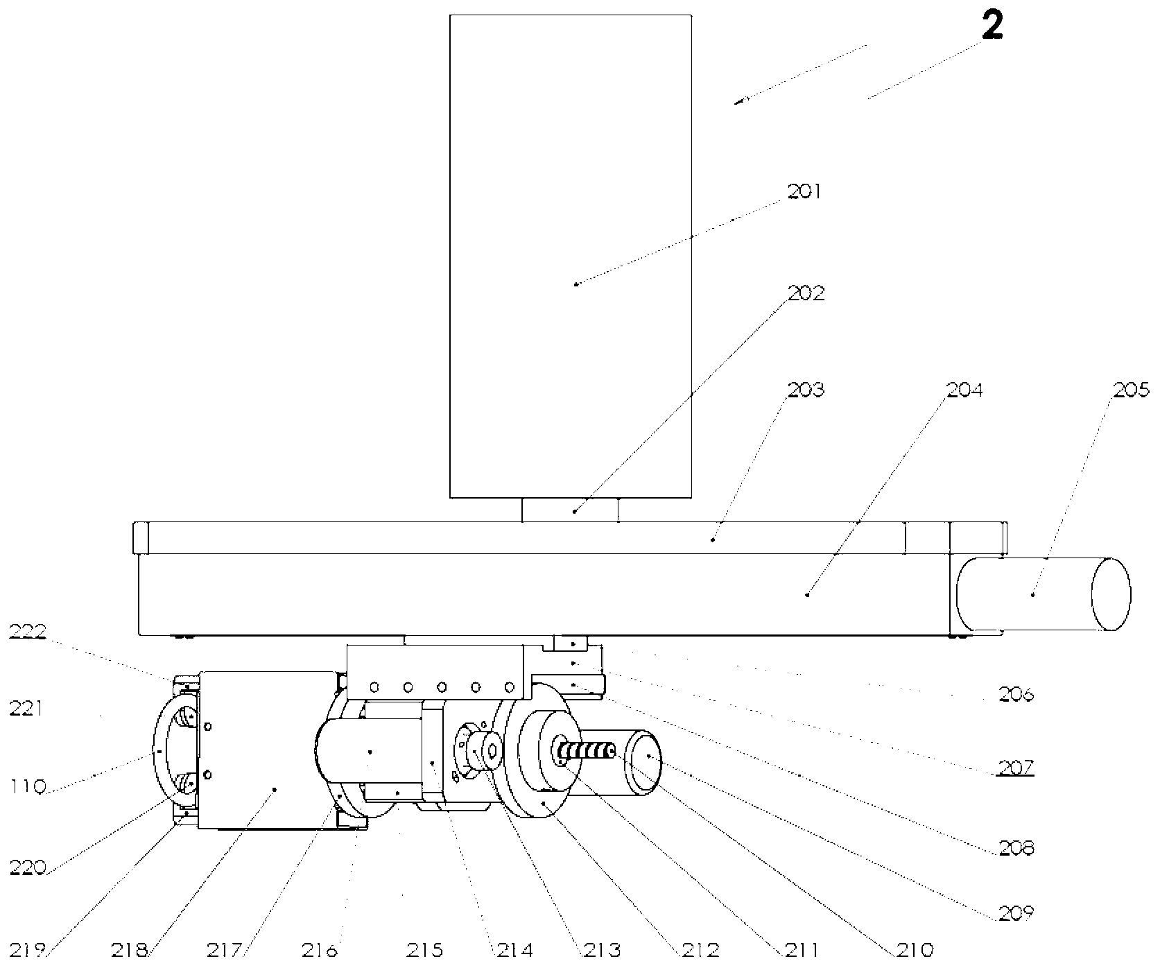
Figure 2 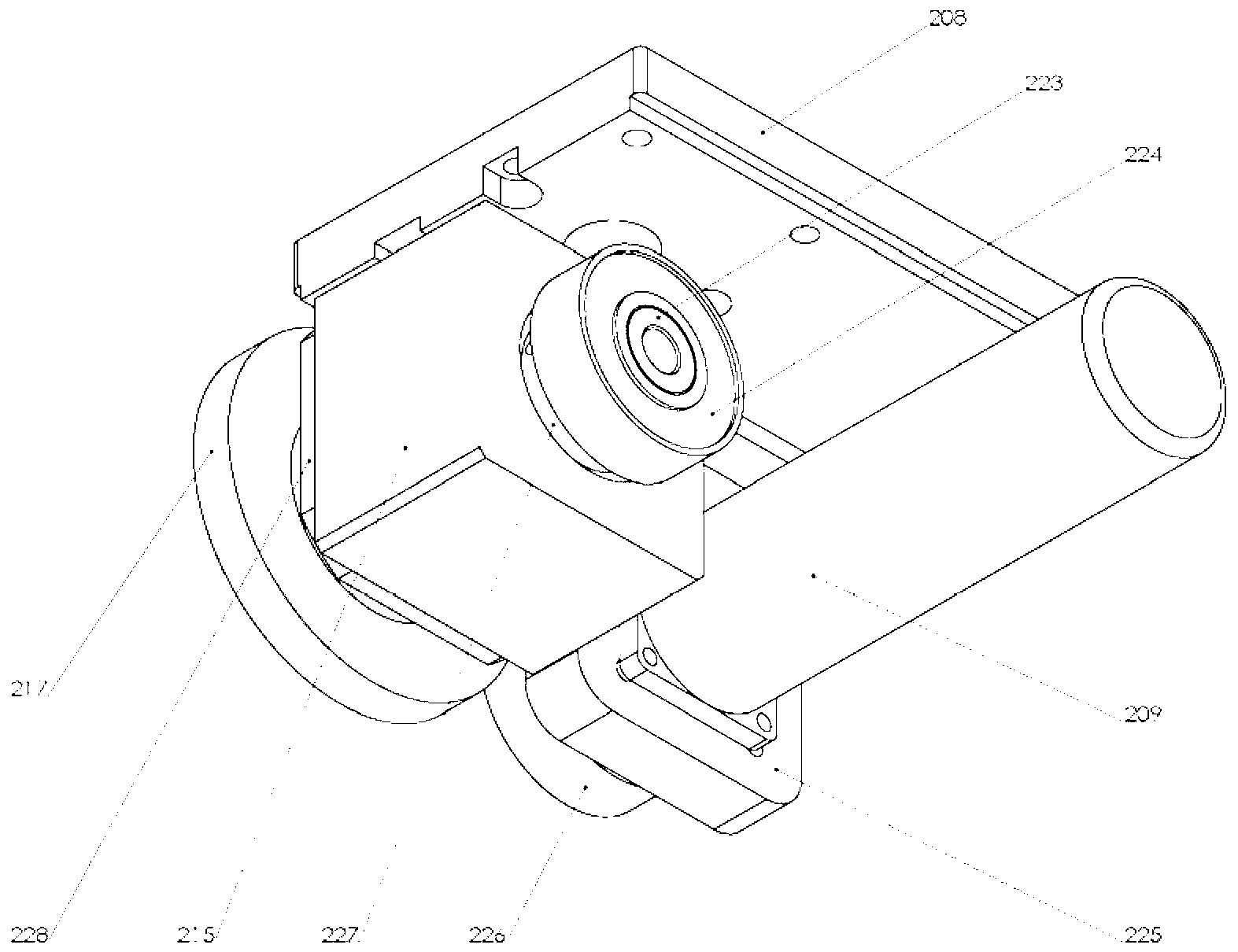
Figure 3
Abstract
Description
technical field
[0001] The invention relates to a precious metal calendering robot, in particular to a precious metal jewelry calendering robot. Background technique
[0002] Precious metal jewelry refers to jewelry and ornaments made of metal materials such as gold and silver. Jewelry types include bracelets, rings, necklaces, earrings, pectorals and wrist ornaments. Among them, bracelets and rings are jewelry worn on people's wrists and fingers. Among the many types of jewelry styles, their styles are the most abundant and have the most symbolic meaning, so many people are willing to wear bracelets and rings.
[0003] Processing precious metal bracelets and ring jewelry, the production process mainly includes steps such as melting gold, pouring mold, holding mold, calendering, car embossing and so on. Wherein, the existing calendering process treatment method is: artificially adopting a pressing knife made of steel or agate to perform repeated calendering treatment on th...
Examples
Embodiment
[0058] A precious metal jewelry calendering robot, characterized in that: it is composed of a frame 1 containing a hanging plate, a manipulator 2 arranged in the frame 1 containing the hanging plate, a tool table 3 and an auxiliary table 4, and the manipulator 2 is arranged on the second On one side of the beam 102, the tool table 3 and the auxiliary table 4 are arranged on the base platform 116, such as figure 1 and Figure 9 shown.
[0059] Described framework 1 that contains hanging plate, its structure is as figure 1 Shown, by the 1st column 111, the 2nd column 115, the 3rd column 117, the 4th column 120 and the 1st beam 101, the 2nd beam 102, the 3rd beam 113, the 4th beam 112, the 5th beam 114, the 6 crossbeams 105, the 7th crossbeam 104, the 8th crossbeam 103, the 9th crossbeam 118, the 10th crossbeam 119, straddling the base platform 116 above the 4th crossbeam 112 and the 5th crossbeam 114, being arranged on the 6th crossbeam 105 The first motor 106 containing the ...