
A kind of X-ray high temperature and high pressure catalytic reactor
A catalytic reaction, high temperature and high pressure technology, applied in the field of catalytic furnaces, can solve problems such as cracking of beryllium sheets, impenetrability of X-rays, pollution, etc., and achieve excellent performance
Patent Information
- Authority / Receiving Office
- CN · China
- Patent Type
- Patents(China)
- Current Assignee / Owner
- Publication Date
- 2015-11-25
- Estimated Expiration
- Not applicable · inactive patent
Smart Images
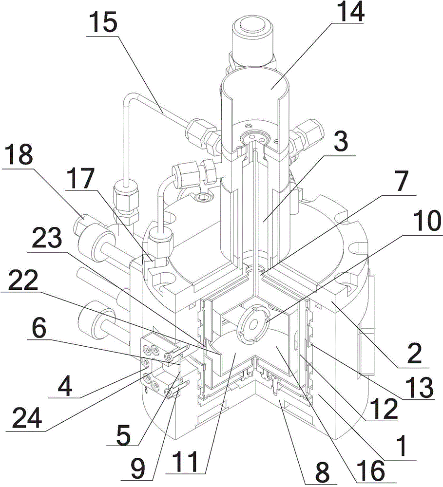
Figure 1 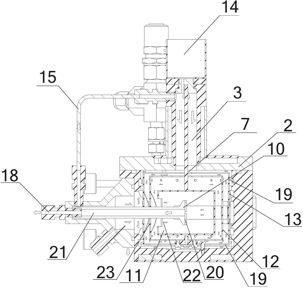
Figure 2 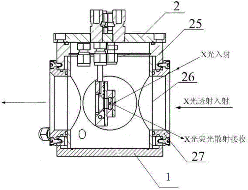
Figure 3
Abstract
Description
technical field
[0001] The invention relates to a catalytic furnace, in particular to an X-ray high-temperature and high-pressure catalytic reaction furnace. Background technique
[0002] At present, most X-ray in-situ catalytic furnaces in China use polymer film materials as window materials, but due to the poor pressure and high temperature resistance of polymer film materials, X-ray catalytic reactors with polymer films as window materials can only To meet some requirements, the structure of the existing X-ray in-situ catalytic furnace is as follows image 3 As shown, the furnace loam cake 2, furnace cavity 1, sealing rubber ring 25, polymer film 26 and sealing flange 27 are connected into a sealed chamber by bolts. In the low-energy range, X-rays are easily absorbed by materials, resulting in the inability of rays to penetrate. Therefore, polymer film materials are used as window materials, but due to poor pressure and high temperature resistance of polymer materials (26...
Examples
Embodiment Construction
[0021] The following will clearly and completely describe the technical solutions in the embodiments of the present invention with reference to the accompanying drawings in the embodiments of the present invention. Obviously, the described embodiments are only some, not all, embodiments of the present invention. Based on the embodiments of the present invention, all other embodiments obtained by persons of ordinary skill in the art without creative efforts fall within the protection scope of the present invention.
[0022] figure 1 It is a schematic structural view of an X-ray high-temperature and high-pressure catalytic reaction furnace in the present invention, as figure 1 As shown, an X-ray high-temperature and high-pressure catalytic reaction furnace includes a base 8, a furnace cavity 1 formed by a cylindrical outer wall, a furnace upper cover 2 and a gas inlet channel 3 located on the furnace cavity, and a communication hole is arranged in the middle of the furnace upp...