
On-line input and exit control method of converters in parallel HVDC transmission system
A technology for high-voltage direct current and power transmission systems, which is applied in the direction of converting AC power input into AC power output, AC power input into DC power output, and irreversible AC power input into DC power output, etc. It can solve the problem that the parallel structure is not mature. Online switching strategy and other issues, to achieve the effect of small reactive power impact, fast switching and simple control logic
Patent Information
- Authority / Receiving Office
- CN · China
- Patent Type
- Patents(China)
- Current Assignee / Owner
- Publication Date
- 2016-06-15
- Estimated Expiration
- Not applicable · inactive patent
Smart Images
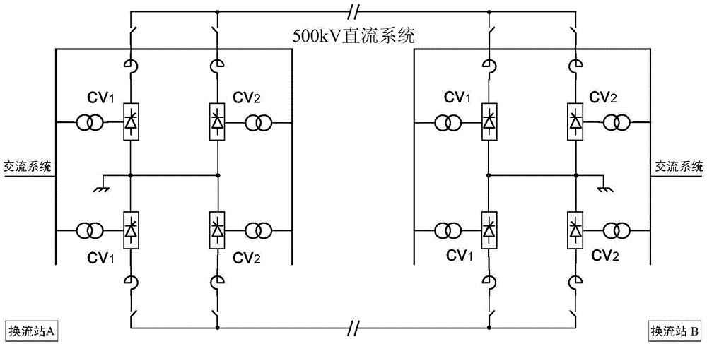
Figure 1 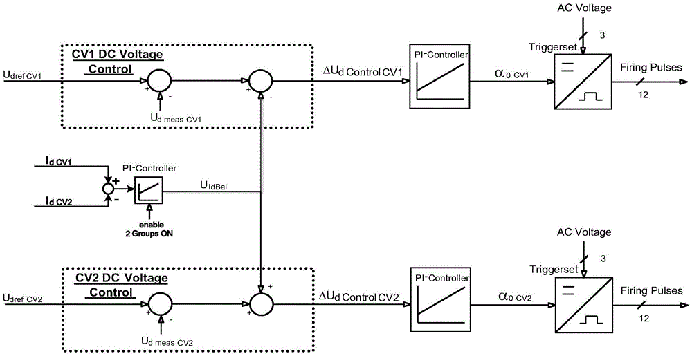
Figure 2 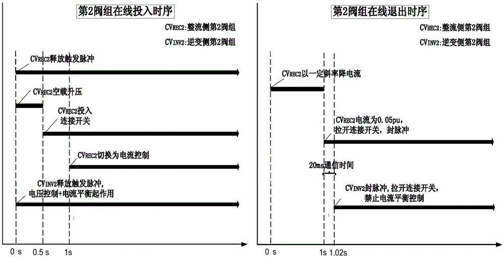
Figure 3
Abstract
Description
technical field
[0001] The invention relates to a method for controlling the on-line switching on and off of a converter in a parallel high-voltage direct current transmission system. Background technique
[0002] In the field of UHVDC transmission, the range of converters in the parallel-connected DC system is large, the expansion of the converter station is relatively flexible, the insulation and coordination of the whole system are convenient, and the operation is economical. The Italy-Corsica-Sardinia three-terminal DC transmission project and the Quebec-New England 5-terminal DC transmission project that have been put into operation in the world all adopt a parallel connection structure.
[0003] The main wiring of multi-converter parallel structure is as follows: figure 1 as shown, figure 1 Indicates a double-terminal system, or a multi-terminal system, each end can be bipolar or single-stage, and each station can run two converters (a group of CV1, CV2) in parallel,...
Examples
Embodiment Construction
[0015] The present invention will be described in further detail below in conjunction with the accompanying drawings.
[0016] In the following descriptions about input and exit, the second converter on the rectification side (that is, the second valve group in the figure) CV REC2 , the second converter CV on the inverter side INV2 Take the converter that needs to be put in or out as an example.
[0017] The principle of current balance control is: when the two converters of each pole on the inverter side are unlocked at the same time, current balance control is performed, such as figure 2 Shown: The inverter current balance control provides an additional voltage modulation value to keep the two voltage groups operating in a balanced manner. Add a DC current measuring point at the outlet of the parallel reactance converter with two ends in parallel at each pole, respectively measure the DC current of the two converters, and calculate the difference between the current IdCV1...