
Hinge pin component and piling machinery
A technology of pin shafts and components, which is applied in the direction of mechanical equipment, pins, connecting components, etc., and can solve problems such as difficult disassembly, spewing out of connecting pin shafts, and falling off of drill pipes, etc.
Patent Information
- Authority / Receiving Office
- CN · China
- Current Assignee / Owner
- Publication Date
- 2014-04-23
- Estimated Expiration
- Not applicable · inactive patent
Smart Images
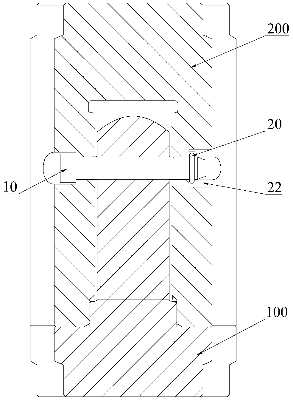
Figure 1 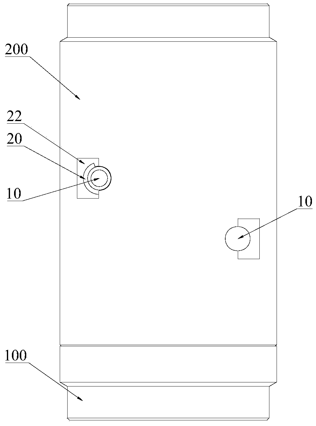
Figure 2 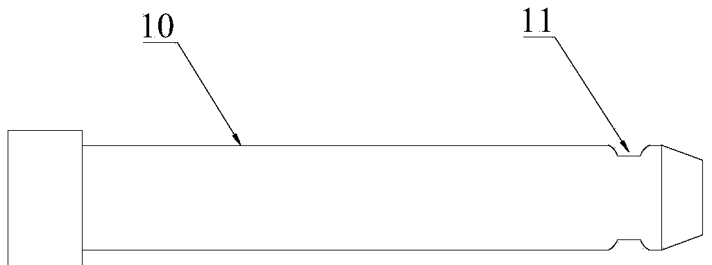
Figure 3
Abstract
Description
technical field
[0001] The invention relates to the technical field of mechanical connection anti-loosening, in particular to a pin shaft assembly and a piling machine provided with the pin shaft assembly. Background technique
[0002] At present, in pile machinery products, the drill pipes and the drill pipe and the drill bit are connected through inner and outer hexagonal joints. Specifically, the inner and outer hexagonal joints are fixedly connected by pin shafts to transmit axial tension. The shaft passes through the inner and outer hexagonal joints, and is fixed at the end with nuts; in addition, in order to prevent the nut from falling off due to the rotation of the pin shaft, which will cause the connection of the two connecting square heads to be separated, a pin is added, and the pin is connected from the inner hexagonal The joint is inserted so that the end of the pin is pressed against the pin shaft to prevent the pin shaft from rotating.
[0003] However, due t...
Examples
Embodiment Construction
[0029] It should be noted that, in the case of no conflict, the embodiments of the present invention and the features in the embodiments can be combined with each other. The present invention will be described in detail below with reference to the accompanying drawings and examples.
[0030] Below in conjunction with accompanying drawing, embodiment of the present invention is described in further detail:
[0031] figure 1 A schematic diagram of the structure of a pin assembly used to connect the inner and outer hexagonal joints provided by the embodiment of the present invention. In order to facilitate understanding, the inner and outer hexagonal joints in this figure are sectional views; figure 2 for figure 1 Schematic diagram of the structure of the pin assembly shown when it is used to connect the inner and outer hexagonal joints; image 3 for figure 1 Schematic diagram of the structure of the pin in the shown pin assembly; Figure 4 It is a structural schematic diag...