
A combined cutting string dust and mist removal device
A device and string cutting technology, which is applied in the field of dust and mist removal devices, can solve the problems of not achieving the effect of dust and mist removal, unfavorable dust, mist droplet removal, and large pressure loss.
Patent Information
- Authority / Receiving Office
- CN · China
- Patent Type
- Patents(China)
- Current Assignee / Owner
- Publication Date
- 2016-04-20
Smart Images
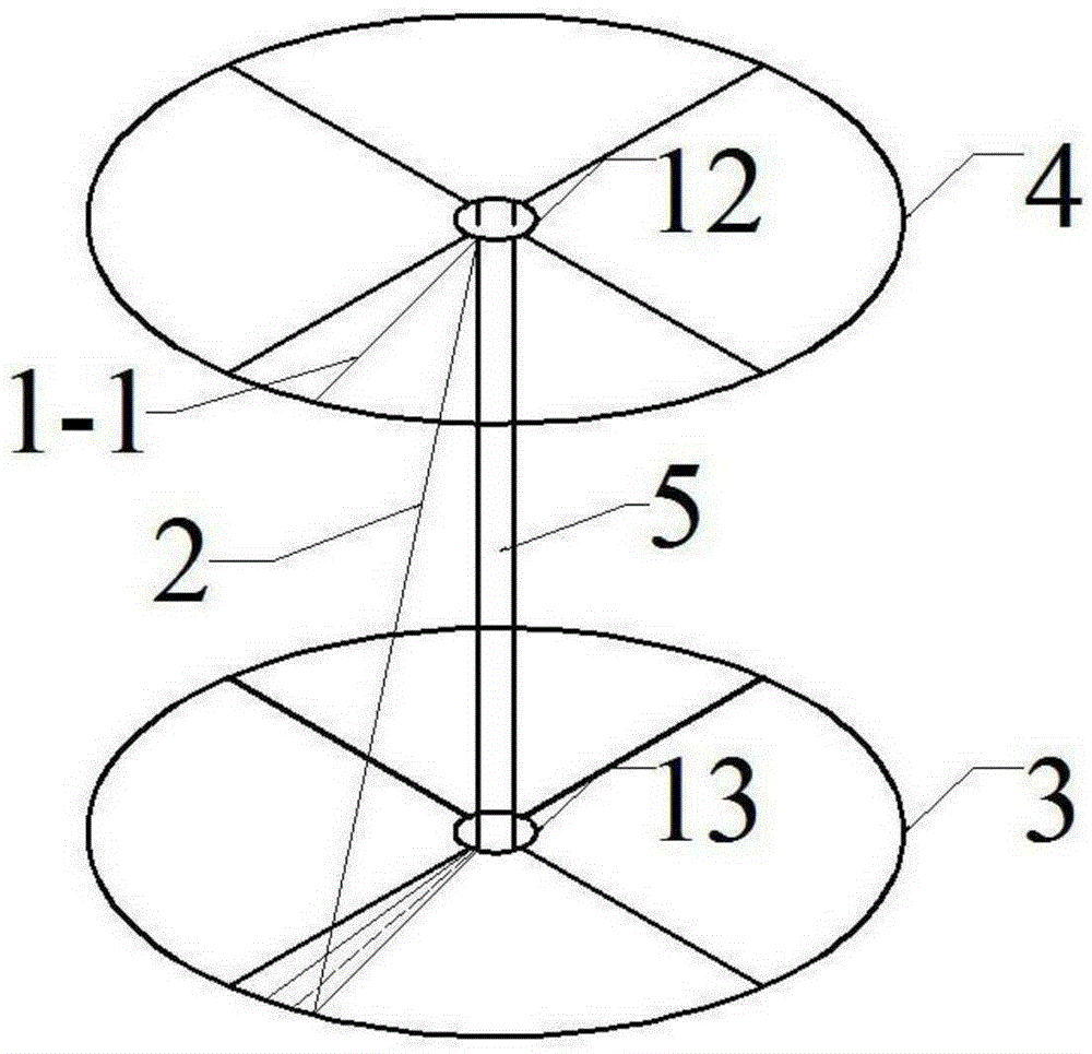
Figure 1 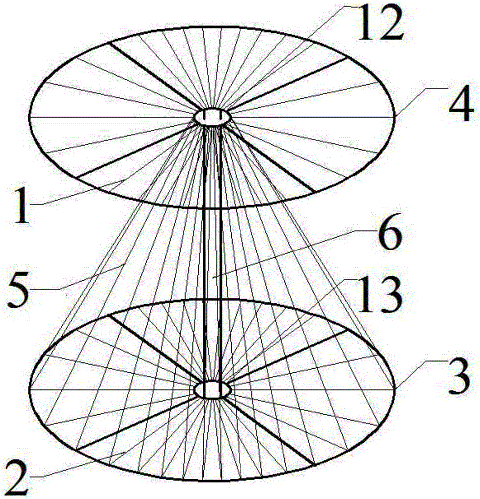
Figure 2 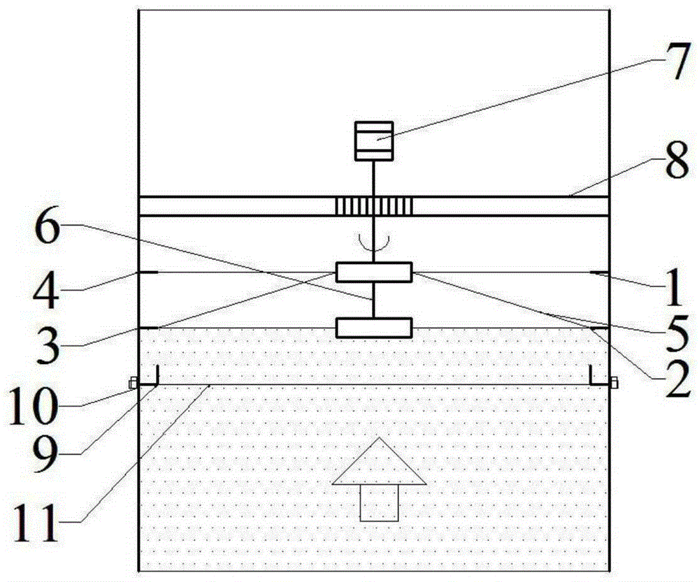
Figure 3
Abstract
Description
technical field
[0001] The invention relates to a dust and mist removal device, in particular to a dust and mist removal device for removing mist and dust in gas by combining cutting strings. Background technique
[0002] Existing mechanical dedusters mainly use impact plates, baffle plates, orifice nets, silk screens or swirl sheets to remove fog droplets or dust, and use the inertia of air molecules to be smaller than that of fog droplets or dust. When encountering an intercepting body, it is easy to change the direction of movement to bypass the intercepting body, and the mist or dust will be intercepted due to the existence of the intercepting body and deviate from the streamline of the airflow, thereby realizing the separation of the mist (dust) from the airflow. The pressure loss of mechanical dust collectors such as plate nets, impact plates, baffles, etc. is very large, and the removal efficiency of small diameter droplets (dust) is low. In addition, the existing dus...
Examples
Embodiment Construction
[0020] The present invention will be further described in detail below in conjunction with the accompanying drawings and specific embodiments.
[0021] Such as image 3 The combined cut-string dedusting and mist removal device shown in the figure includes a dust and mist removal device, a motor 7, a motor support ring 8, a water collection tank 9, a drain valve 10, and an intercepting net 11. The connection in the dust and mist removal device One end of the shaft 6 tail is connected with the motor 7 through a bearing, and the end of the connecting shaft 6 tail is the end in the downwind direction, and the installation of the motor 7 in the downwind direction helps reduce resistance and improve the service life of the motor.
[0022] The motor 7 is fixed on the motor support ring 8, and the motor support ring 8 is fixed in the cylinder body. A water collection tank 9 is arranged on the cylinder body at a certain distance from the lower end of the dust and mist removal device, a...