
Water-source heat pump water-saving high-efficiency recharge system
A technology of water source heat pumps and water source heat pump units, applied in heat pumps, heating devices, geothermal energy power generation, etc., can solve problems such as increasing water intake, increasing initial investment costs, increasing equipment wear, etc., to improve operating efficiency, control and adjust Convenience and the effect of preventing well accidents
Patent Information
- Authority / Receiving Office
- CN · China
- Patent Type
- Patents(China)
- Current Assignee / Owner
- Publication Date
- 2016-02-03
Smart Images
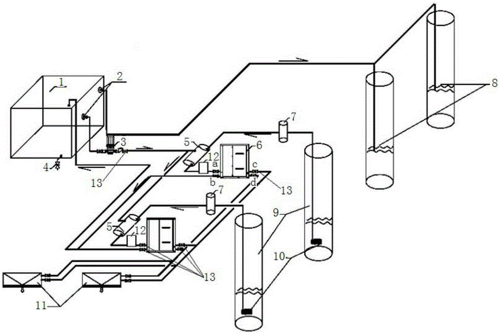
Figure 1 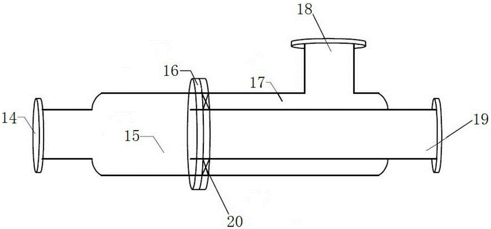
Figure 2
Abstract
Description
technical field
[0001] The utility model relates to a water-saving and high-efficiency recharge system for a water source heat pump. Background technique
[0002] The most common problem with current water source heat pumps is that the extracted groundwater is difficult to fully recharge after being used by the heat pump, and the phenomenon of stolen drainage is very serious, wasting precious groundwater resources. The reason is that recharge wells often occur. This is because the directly extracted raw water (especially surface water) generally contains a large amount of impurities such as fine sand. If it is directly used for recharge, it is easy to plug the well. In addition, it contains If the water with a lot of impurities is directly supplied to the water source heat pump unit, it will not only easily cause pipeline blockage, but also increase the wear and tear of the equipment, which will seriously affect the working efficiency and service life of the equipment, and b...
Examples
Embodiment Construction
[0014] Below in conjunction with accompanying drawing, the specific embodiment of the present utility model will be further described.
[0015] The utility model is realized in this way, which includes: a water separation treatment device 1, a filter 2, a water source heat pump unit 6, a swirl sand remover 7, a return well 8, a water well 9, a submersible pump 10, and a fan coil unit 11 And throttle valve 13, its structure is: it also includes heat pump water supply pump 3 and water mixer 5, one end of said heat pump water supply pump 3 is connected to water mixer 5 through pipeline, and the other end is connected with water separation treatment through pipeline The filter 2 on the upper part of the device 1 is connected, and the water separation treatment device 1 and the return well 8 are connected through pipelines; the water mixer 5, the cyclone sand remover 7 and the submersible pump 10 located in the pumping well 9 are sequentially connected in series. On the same pipeli...