
Device and method for finding faults of loop current in direct current system
A DC system and fault finding technology, applied in power supply testing, dielectric strength testing and other directions, can solve the problems of increasing the workload of the staff, relying on manual operation, low efficiency, etc., to reduce the workload, reduce the difficulty of finding, and improve reliability. sexual effect
Patent Information
- Authority / Receiving Office
- CN · China
- Patent Type
- Patents(China)
- Current Assignee / Owner
- Publication Date
- 2017-01-25
Smart Images
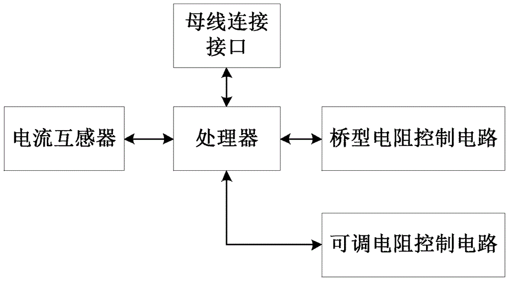
Figure 1 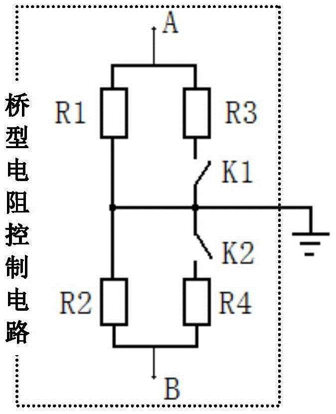
Figure 2 
Figure 3
Abstract
Description
technical field
[0001] The invention relates to a direct current system fault finding technology, in particular to a device and method for finding a direct current system loop current fault finding. Background technique
[0002] At present, during the operation of the DC power system of the substation, there will be a loop fault between the two DC systems, which will affect the normal operation of the DC power system of the substation. In order to ensure the reliable operation of the DC power system of the substation, the staff must detect the loop current fault in time and accurately select and locate the line. However, the existing detection methods basically rely on manual operations, so this will not only increase the workload of the staff, but also have low efficiency. In addition, there are still hidden dangers in the existing detection methods, such as the AC signal injection method. Contents of the invention
[0003] In order to solve the above-mentioned technica...
Examples
Embodiment Construction
[0049] Such as figure 1 As shown, a DC system loop current fault finding device includes insulation monitoring equipment, the insulation monitoring equipment includes a processor, and the processor is respectively connected with a bus connection interface, a bridge resistance control circuit, an adjustable resistance control circuits and current transformers. The processor is also connected with a host computer, and the processor is connected with the host computer through communication.
[0050] As a further preferred embodiment, the bridge circuit control circuit includes a first resistor, a second resistor, a third resistor, a fourth resistor, a first switch, and a second switch;
[0051] One end of the first resistor is connected to one end of the second resistor, the other end of the second resistor is connected to one end of the fourth resistor, and the other end of the fourth resistor is connected to a connection end of the second switch, so The other connection end o...