
Device for positioning an object in space
A positioning device and target positioning technology, applied in the field of positioning devices or micro-moving positioning devices, can solve problems such as loss of dimensional stability, achieve good distribution, and solve the effect of dimensional stability problems
Patent Information
- Authority / Receiving Office
- CN · China
- Patent Type
- Applications(China)
- Current Assignee / Owner
- Publication Date
- 2014-12-10
Smart Images
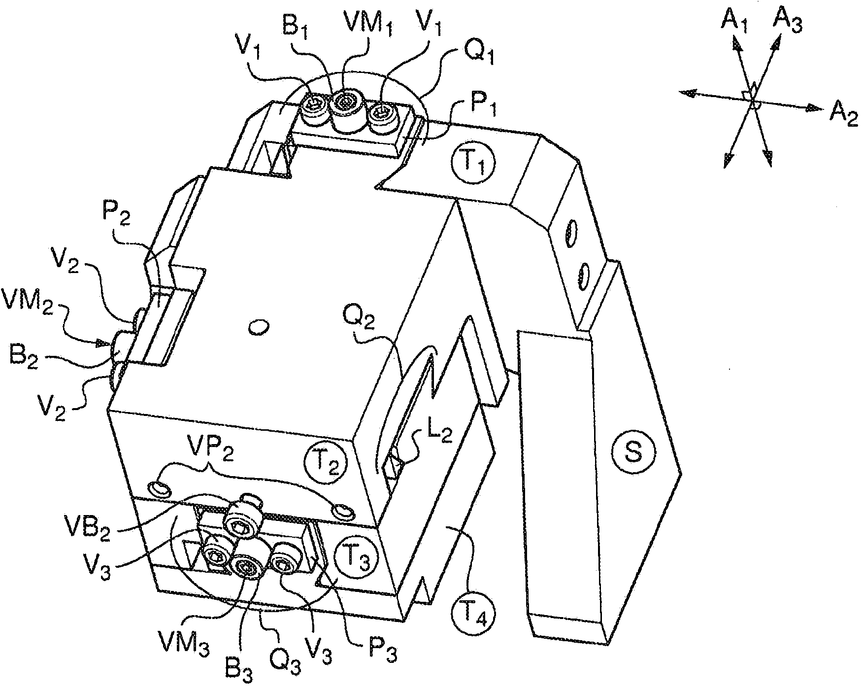
Figure 1 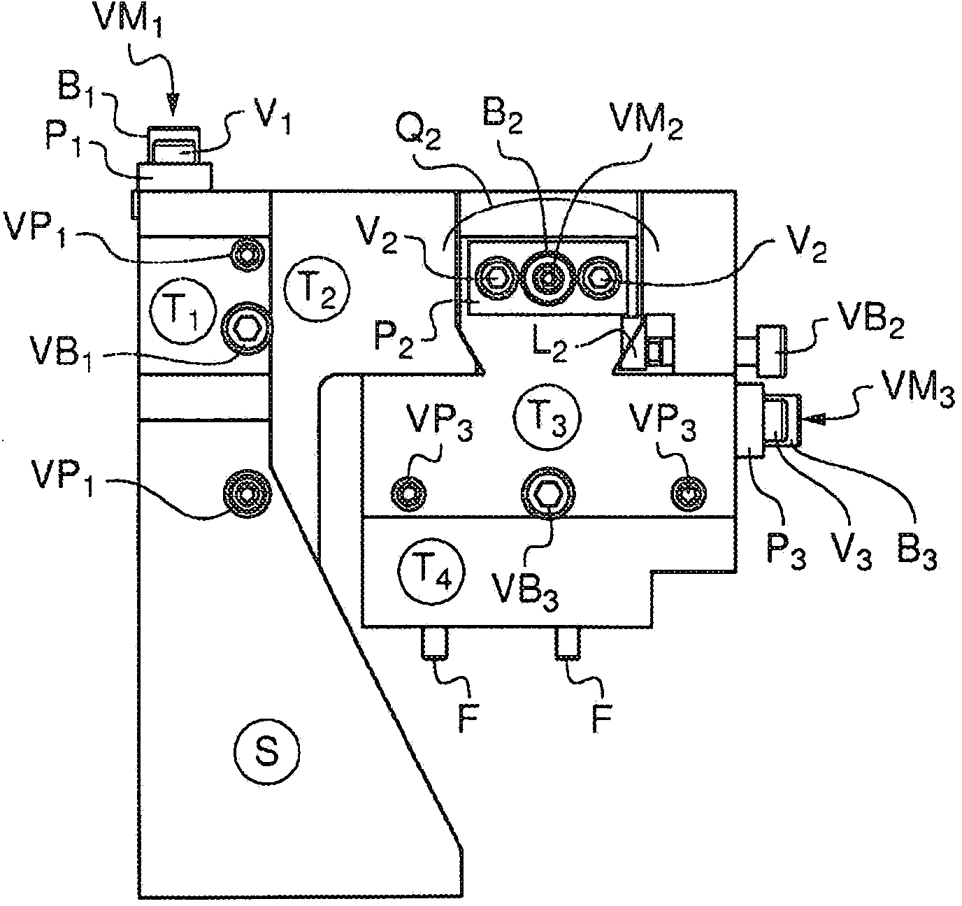
Figure 2 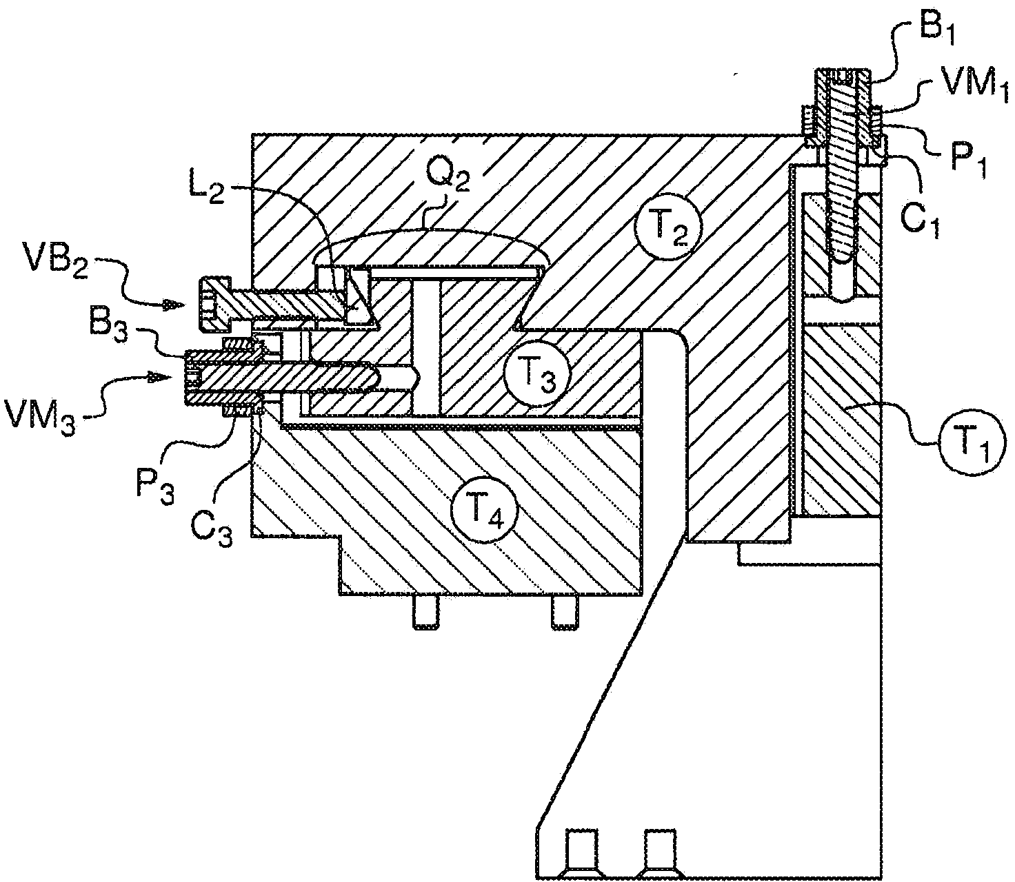
Figure 3
Abstract
Description
technical field
[0001] The present invention relates to the field of positioning devices for positioning objects in space, and more precisely to the field of ultra-precise or micro-motion positioning devices for positioning objects in space, especially in applications such as flux micrometry The field of positioning devices used in measuring equipment. Background technique
[0002] Flux micrometry is a technique that enables high-speed sequential delivery of particles, molecules or cells carried by a carrier fluid to a light excitation source, such as a light beam, advantageously a laser beam. This technique allows, inter alia, to classify and classify said particles, molecules or cells quantitatively and / or qualitatively, respectively, quantitatively and / or qualitatively, based on the analysis of optical and / or physical signals emitted by said particles, molecules or cells passing through said optical excitation source. / or counting and / or feature determination.
[0003] ...
Examples
Embodiment Construction
[0062] figure 1 is a three-dimensional view of an implementation variant of the device of the present invention, showing the four plates (T1, T2, T3 and T4) of the device, and the possibility to make the plates T1 and T2 (Q1), T2 and T3 (Q2) and T3 and T4 (Q3) a dovetail pin / groove system (Q) that moves relative to the other.
[0063] Note that for each pin / tongue-and-groove system there is one microscrew VM (VM1 for system Q1, VM2 for system Q2, VM3 for system Q3). Each microscrew VM is held connected to the plate with said microscrew by a ring B (B1, B2 and B3), which is itself supported by a mounting plate P (P1, P2 , P3), said mounting plate P (P1, P2, P3) itself is held by two screws V (V1 for ring B1, V2 for ring B2, V3 for ring B3).
[0064] It is to be noted that on plate T2 a locking screw (VB2) is visible which acts on the pin / tongue and groove system Q2 (the locking screws VB1 and VB3 acting on the pin / tongue and groove system Q1 and Q3 are not shown on the figure...