
Excavator control system with oil hybrid power
An oil-liquid mixing and control system technology, applied in the direction of earth mover/shovel, construction, etc., can solve the problems of energy waste, large size of system components, high price, reduce heat generation, simplify system design, and improve recovery efficiency Effect
Patent Information
- Authority / Receiving Office
- CN · China
- Patent Type
- Applications(China)
- Current Assignee / Owner
- Publication Date
- 2015-01-28
Smart Images
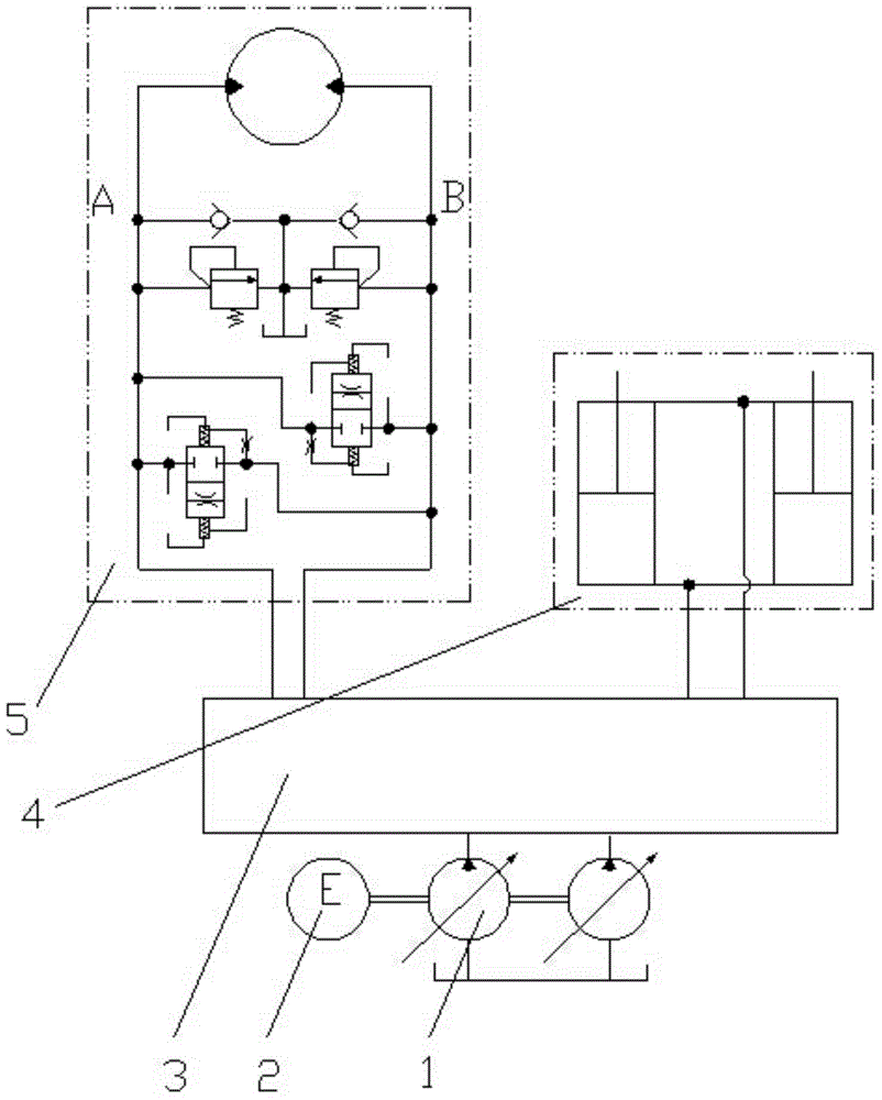
Figure 1 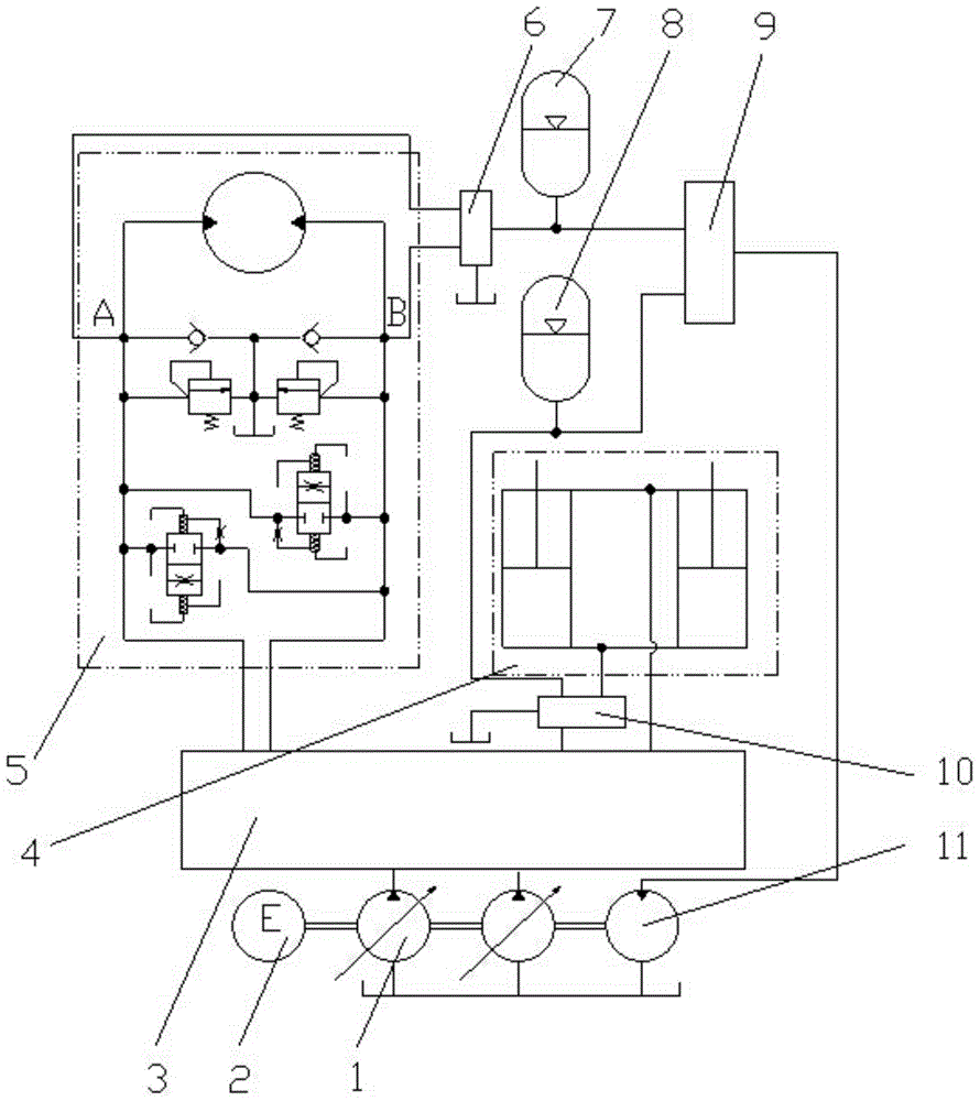
Figure 2 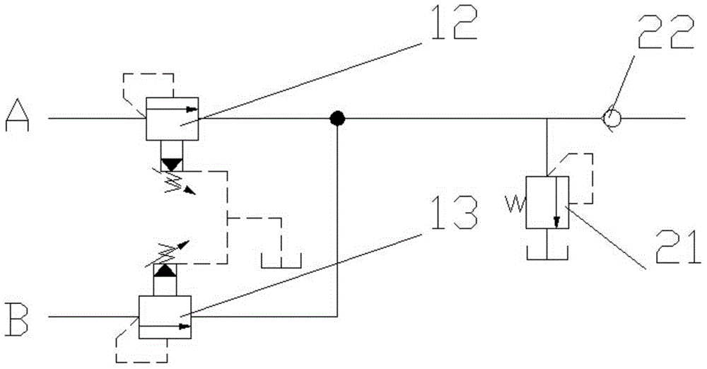
Figure 3
Abstract
Description
technical field
[0001] The invention relates to a hydraulic excavator control system, in particular to an oil-liquid hybrid power excavator control system, which belongs to the technical field of engineering machinery. Background technique
[0002] Due to its large consumption, high fuel consumption and poor emission, hydraulic excavators have gradually become the object of general attention in the field of energy conservation and environmental protection. The control system of the existing hydraulic excavator such as figure 1 As shown, the engine 2 drives the hydraulic pump 1 to extract the hydraulic oil in the oil tank and sends it to the hydraulic swing motor 5 and the boom cylinder 4 through the main control valve 3 . Due to the large mass of the turntable, boom, stick and bucket of the hydraulic excavator, a large amount of inertial energy will be released when decelerating or braking. An effective way to solve this problem is to perform energy recovery. Generally, th...
Examples
Embodiment Construction
[0024] The present invention will be further described below in conjunction with accompanying drawing.
[0025] Such as figure 2 As shown, an oil-hydraulic hybrid excavator control system includes a hydraulic pump 1, an engine 2, a main control valve 3, a boom cylinder 4, a swing motor 5, a swing energy recovery valve 6 and a boom potential energy recovery valve 10, The two oil inlets of the rotary energy recovery valve 6 are respectively connected to the A port and the B port of the rotary motor 5, and the oil outlet of the rotary energy recovery valve 6 is connected to the rotary accumulator 7;
[0026] The oil inlet of the boom potential energy recovery valve 10 is connected with the rodless cavity of the boom cylinder 4, and the oil outlet of the boom potential energy recovery valve 10 is connected with the boom accumulator 8;
[0027] The oil outlets of the slewing accumulator 7 and the boom accumulator 8 are connected with the oil inlet of the energy release control va...