
Method for obtaining vibration stress of rotor vane of engine
A technology for rotor blades and vibration stress, which is applied in vibration testing, mechanical component testing, and machine/structural component testing. , the effect of low test cost
Patent Information
- Authority / Receiving Office
- CN · China
- Patent Type
- Applications(China)
- Current Assignee / Owner
- Publication Date
- 2015-04-01
Smart Images
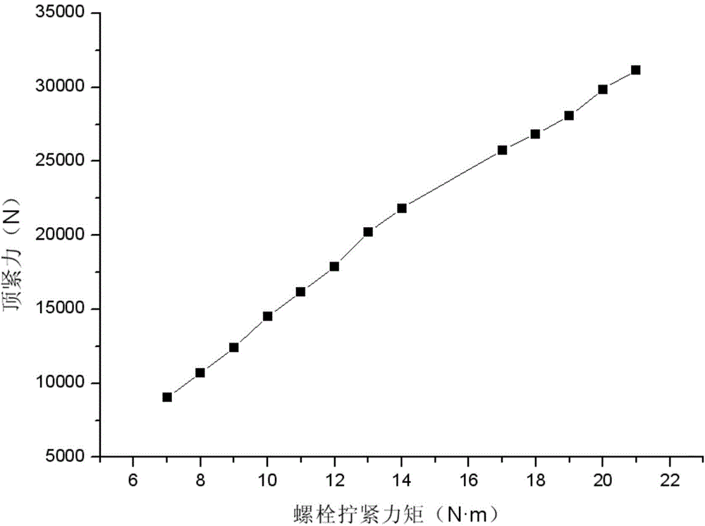
Figure 1 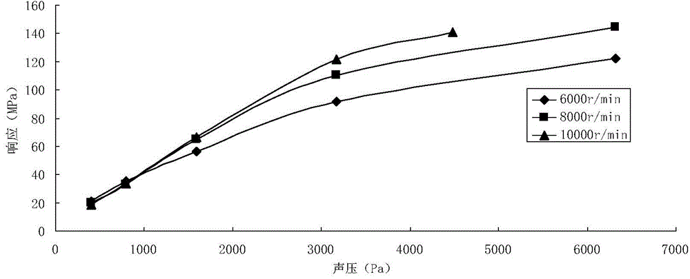
Figure 2 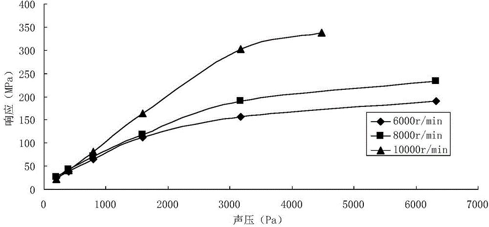
Figure 3
Abstract
Description
technical field
[0001] The invention relates to the field of aero-engine structural strength, in particular to a static test method for obtaining vibration stress of engine rotor blades. Background technique
[0002] Engine rotor blades are one of the key components of aero-engines, and their working conditions are harsh. The rotor blades not only bear large centrifugal loads and high blade tip speeds when rotating at high speeds, but also are in complex fields coupled with flow fields, temperature fields, and sound fields. Under the working environment, its static stress and dynamic stress levels are relatively high. Vibration stress is one of the main stress states of rotor blades when they are working, and the vibration stress of rotor blades mainly comes from airflow disturbance, noise excitation or vibration transmitted by blade discs. For example, Tao Chunhu et al. wrote, Failure and Prevention of Aeroengine Rotating Parts, National Defense Industry Press, ISBN978-7-1...
Examples
Embodiment 1
[0031] The invention provides a method for obtaining the vibration stress of an engine rotor blade, which specifically includes the following steps:
[0032] S1. Using traveling wave sound field to simulate noise excitation;
[0033] S2. Use the blade root clamping force method to simulate the blade root force boundary caused by the rotating speed, and install the rotor blade test piece on the fixture according to the blade root force boundary;
[0034] S3. Obtain the maximum root mean square principal stress at the maximum vibration stress part of the rotor blade by means of a dynamic strain test.
[0035] In this embodiment, in the step S1, the requirements of the test for the noise spectrum are met through the design of the traveling wave tube and the closed-loop control of the sound field, and the requirements for the direction of the noise excitation are met through the design of the installation fixture. Specifically, a small circular cross-section traveling wave tube i...
Embodiment 2
[0050] Similar to Embodiment 1, the difference is that this embodiment adopts single-frequency sound excitation, including the following steps:
[0051] S1. Using traveling wave sound field to simulate noise excitation;
[0052] S2. Use the blade root clamping force method to simulate the blade root force boundary caused by the rotating speed, and install the rotor blade test piece on the fixture according to the blade root force boundary;
[0053]S3. Obtain the maximum root mean square principal stress at the maximum vibration stress part of the rotor blade by means of a dynamic strain test.
[0054] In this embodiment, in the step S1, the requirements of the test for the noise spectrum are met through the design of the traveling wave tube and the closed-loop control of the sound field, and the requirements for the direction of the noise excitation are met through the design of the installation fixture. Specifically, a circular traveling wave tube with a small cross-section ...