
Rescue device for failure emergency of separation of aircraft undercarriages from runways
A landing gear and aircraft technology, applied in the field of aircraft emergency rescue, can solve the problems that the aircraft cannot be towed and dragged away from the runway or flight area, occupies the airport runway for a long time, and affects the safety of landing aircraft, etc., so as to ensure the mobility performance and overall structural layout Compactness and improved work efficiency
Patent Information
- Authority / Receiving Office
- CN · China
- Current Assignee / Owner
- Publication Date
- 2015-05-06
Smart Images
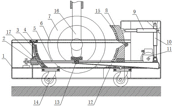
Figure 1 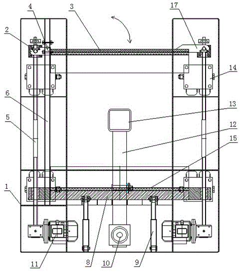
Figure 2 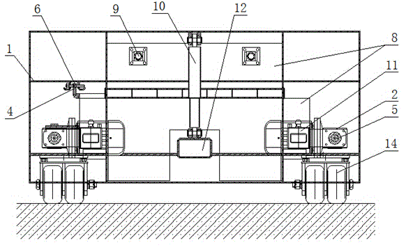
Figure 3
Abstract
Description
technical field
[0001] The invention belongs to the technical field of aircraft emergency rescue, and in particular relates to a rescue device for emergency escape from a runway when an aircraft landing gear fails. Background technique
[0002] The tires of the landing gear of the aircraft are an important part of the aircraft, and play a pivotal role in the parking of the aircraft and during the taxiing, lifting and landing of the aircraft to protect the safety of the aircraft. In actual operation, the tires of aircraft landing gear are affected by various hazards, and tire bursts and brake lock failures may occur. When the aircraft has a tire blowout or brake lock, the usual fault handling method is: use a jack or a lifting device to lift the faulty tire off the ground at the fault rescue site, and then replace the tire and troubleshoot. The problem with this method is that on-site troubleshooting can only be carried out on the airport runway, and the aircraft cannot be t...
Examples
Embodiment 1
[0028] like Figure 1-3 Shown: an aircraft landing gear failure emergency runway rescue device, including a U-shaped frame body 1 with a plurality of load-bearing universal wheels 14 at the bottom and an aircraft tire lifting mechanism and a locking mechanism arranged on the frame body 1, The frame body 1 is provided with an outer casing to prevent dust and rain and protect internal mechanical components. The lifting mechanism includes a lifting lever 12 arranged in the middle of the frame body 1. The middle part of the lifting lever 12 is hinged with the frame body 1. The front end is provided with a lifting plate 13 with a groove, and the rear end is connected with the frame body. The vertical telescopic hydraulic cylinder 10 on the body 1 is connected, and through leverage, when the vertical telescopic hydraulic cylinder 10 pushes the rear end of the lifting lever 12 downward, its front end rises, and the lifting lever placed in the groove of the lifting plate 13 Aircraft ...
Embodiment 2
[0030] like Figure 4 , Figure 5 As shown: the difference between this embodiment and the first embodiment is that the rear locking member 3 of the locking mechanism is arranged in the cavities on both sides of the frame body 1 through telescopic arms, and the rear locking parts 3 arranged in the cavity The lock hydraulic cylinder 21 is driven by forward and backward displacement. The telescopic arm includes a fixed arm 18 and two inner positioning movable arms 19 which are sequentially sleeved in the fixed arm 18. The telescopic hydraulic cylinder 20 is driven to realize telescopic movement, and the rear locking member 3 is arranged on the movable arm 19; the telescopic arm includes a corresponding left telescopic arm and a right telescopic arm, and the left and right telescopic arms pass through mutually matched positioning blocks It is positioned and docked with the positioning groove structure 23. The upper locking block of the front locking part 8 is connected with the...