
Pull rod mechanism
A pull-rod mechanism and pull-rod technology, which is applied to conveyor objects, transportation and packaging, etc., can solve the problems of complex operation, high installation accuracy, and increase equipment production costs, and achieve the goal of reducing installation accuracy, improving production efficiency, and easy program control. Effect
Patent Information
- Authority / Receiving Office
- CN · China
- Patent Type
- Applications(China)
- Current Assignee / Owner
- Publication Date
- 2015-07-29
- Estimated Expiration
- Not applicable · inactive patent
Smart Images
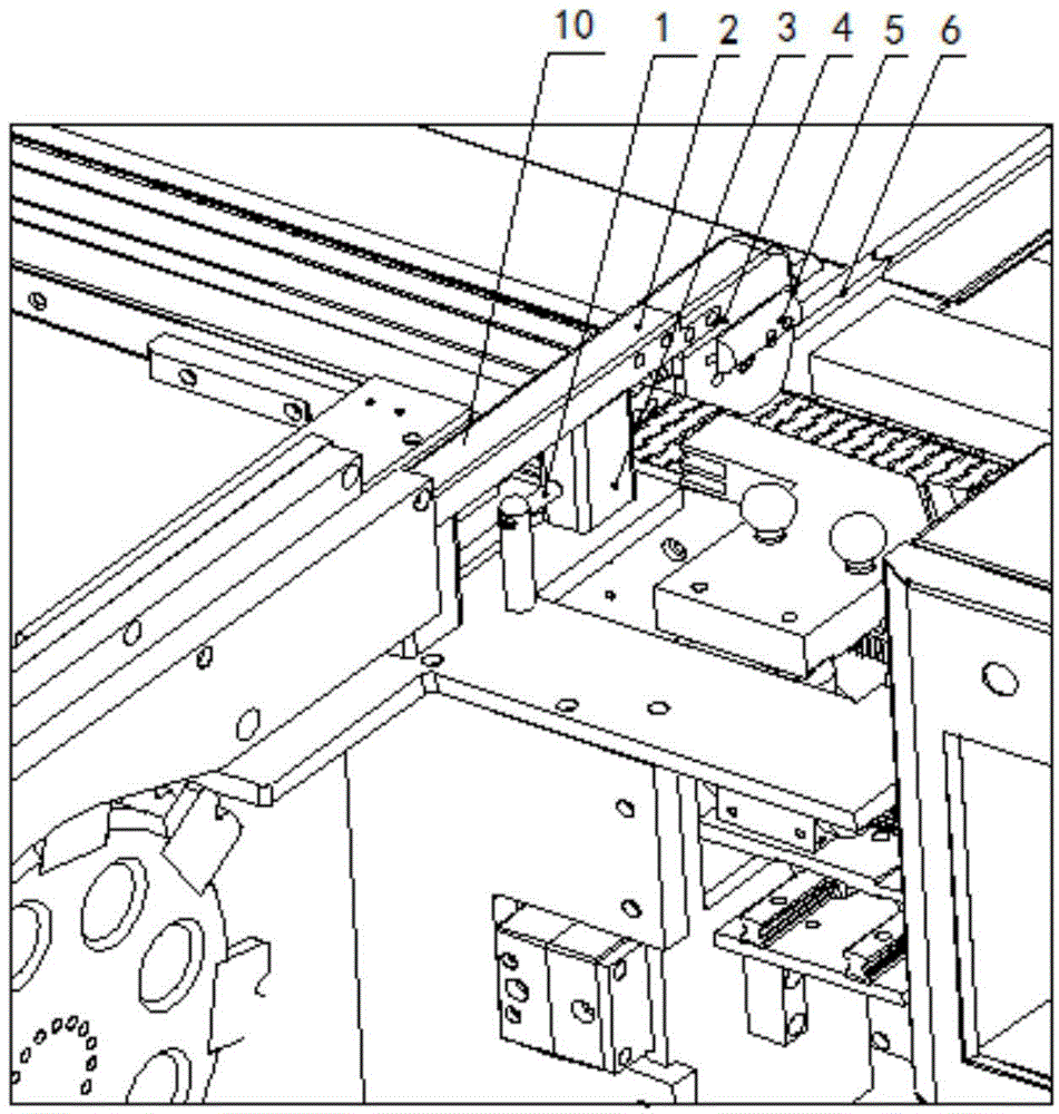
Figure 1 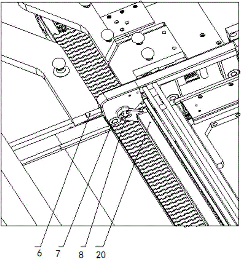
Figure 2
Abstract
Description
technical field
[0001] The invention relates to a pull rod mechanism for automatic material feeding and discharging of a freeze dryer, in particular to a pull rod mechanism. Background technique
[0002] With the improvement of the requirements of the new version of GMP, pharmaceutical factories have higher and higher requirements for sterility and unmanned operation. Fully automatic transfer to the capping machine, the sterility of pharmaceutical production is guaranteed, and human resources are saved. However, the initial cost of equipment procurement is relatively high, and reducing the production cost of our equipment has become a major topic for us.
[0003] Our loading and unloading is a structure that goes forward and out, and the pull rod for discharging adopts a unique "nine-section whip" structure, which saves installation space. The head of the pull rod turns up when it enters the plate of the freeze dryer, and the pull rod walks on the upper part of the vial un...
Examples
Embodiment Construction
[0013] The embodiments of the present invention will be further described in detail below in conjunction with the accompanying drawings.
[0014] see Figure 1-2 , a pull rod mechanism provided by the present invention includes a vial pull rod 20 and two sets of identical overturn assemblies 10, the overturn assemblies 10 are respectively arranged at both ends of the vial pull rod 20, and the overturn assembly 10 controls the movement of the vial pull rod 20. The overturn assembly 10 includes a overturn body 4, a rotating shaft 8 and a down bumper 6. Each end of the vial pull rod 20 is connected to the overturn body 4 through the rotation shaft 8, and the down over bump 6 is connected with the rotating shaft 7. The pull bar mechanism also includes an upturn Lever 1 and upturning bumper 5, upturning bumper 5 is arranged on the turning body 4, and is connected with rotating shaft 8, and upturning bumper 1 is fixed on the moving path of upturning bumper 5, in practical applicatio...