
Float type vacuum breaker valve
A technology of vacuum breaking valve and floating ball, which is applied in the direction of safety valve, balance valve, valve device, etc., can solve the problems of endangering personal safety, wasting liquid resources of vacuum system, breathing valve and floating ball valve can not meet the functional requirements, etc., to achieve The effect of preventing the vacuum from being too low and protecting the waste of liquid resources
Patent Information
- Authority / Receiving Office
- CN · China
- Patent Type
- Patents(China)
- Current Assignee / Owner
- Publication Date
- 2018-01-26
Smart Images
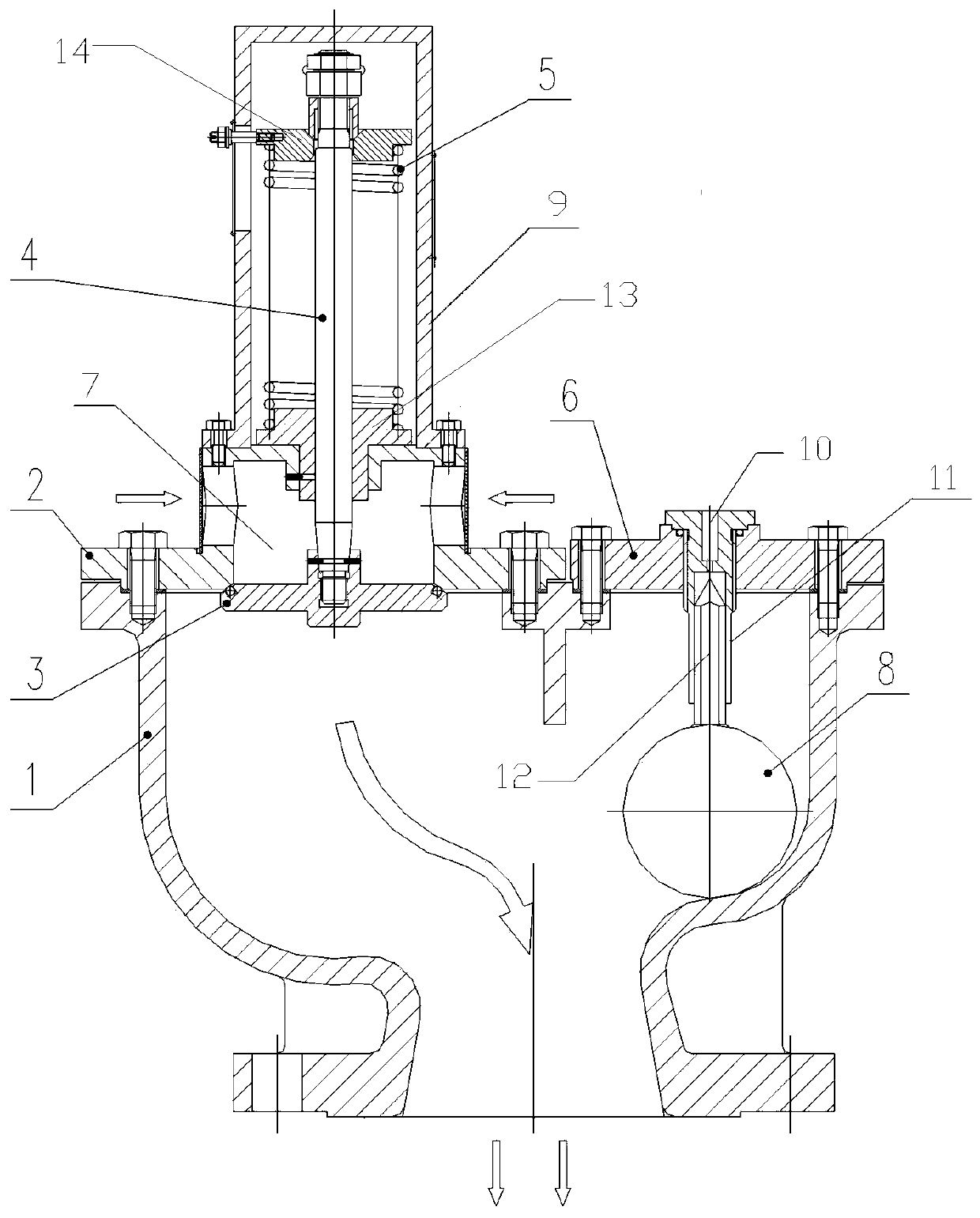
Figure 1
Abstract
Description
technical field
[0001] The invention relates to a floating ball type vacuum breaker valve on a vacuum system which is equipped with air suction, air release and liquid leakage prevention. Background technique
[0002] The condenser system of a nuclear power plant requires a vacuum breaker valve with the functions of negative pressure suction, positive pressure exhaust and liquid leakage prevention. None of the existing breathing valves and float valves can meet the functional requirements. Although the breathing valve has the functions of negative pressure suction and positive pressure exhaust, it cannot prevent the leakage of liquid in the vacuum system. Once the dangerous liquid in the vacuum system leaks out, it will cause serious pollution to the external environment and waste the vacuum system. Liquid resources in . Although the float valve has the functions of positive pressure exhaust and liquid leakage prevention, it cannot meet the requirements of negative pressur...
Examples
Embodiment Construction
[0009] Below in conjunction with accompanying drawing, the present invention is described in detail.
[0010] In order to make the object, technical solution and advantages of the present invention clearer, the present invention will be further described in detail below in conjunction with the accompanying drawings and embodiments. It should be understood that the specific embodiments described here are only used to explain the present invention, not to limit the present invention.
[0011] Such as figure 1 As shown, the present invention includes a valve body 1 communicated with the vacuum system, a valve seat 2 installed on the valve body 1 and a guide sleeve 13 for guiding the valve stem 4, and the guide sleeve 13 is fastened on the valve seat 2; 2 is provided with an air inlet 7; the valve stem 4 extends through the guide sleeve 13 into the interior of the valve body 1, and its front end is provided with a valve disc 3 that cooperates with the valve seat 2 to close the ai...