
Compression ring lock for torque transmission devices and clutch devices or clutches
A technology of a torque transmission device and a clutch device, which is applied in the fields of torque transmission devices and pressure ring locking parts, and can solve problems such as installation space requirements
Patent Information
- Authority / Receiving Office
- CN · China
- Patent Type
- Patents(China)
- Current Assignee / Owner
- Publication Date
- 2020-06-16
Smart Images
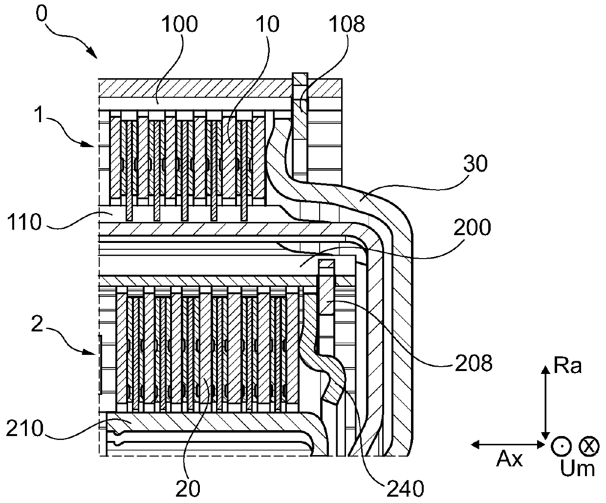
Figure 1 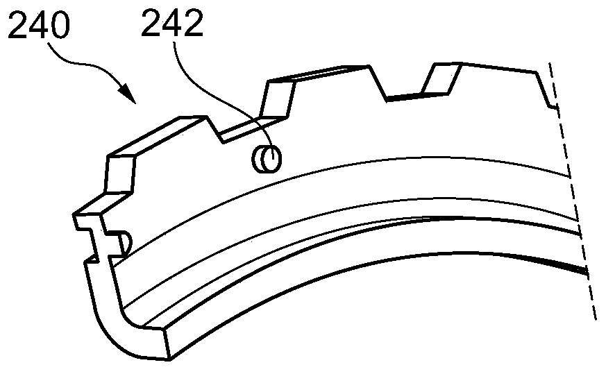
Figure 2 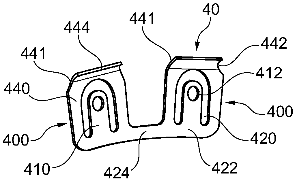
Figure 3
Abstract
Description
technical field
[0001] The invention relates to a torque transmission device, preferably a clutch device or a pressure ring lock of a clutch, for a drive train of a vehicle, in particular a motor vehicle. The invention also relates to a method for securing a clutch arrangement or a clutch connection, preferably a bayonet lock. Furthermore, the invention relates to a clutch device or a clutch and a torque transmission device, in particular a wet-running double clutch. Background technique
[0002] The internal combustion engine of a motor vehicle only makes available power to the driver of the motor vehicle within a defined rotational speed range. In order to be able to use this speed range for different driving states of the motor vehicle, the motor vehicle requires a transmission that can be shifted automatically or manually. This transmission is mechanically coupled to the internal combustion engine via a clutch. A plurality of clutches are used in the drive train of a ...
Examples
Embodiment Construction
[0024] The following explanation of the invention relates to the axial direction Ax, the axis of rotation Ax, the radial direction Ra and the circumferential direction Um around a torque transmission device 0 of a vehicle, in particular a motor vehicle with a gasoline or diesel engine. These position specifications also relate, for example, to the crankshaft, drive train and transmission of the motor vehicle. exist figure 1 The torque transmission device 0 shown in is configured as a wet-running dual clutch with two clutches 1 , 2 , two clutch devices 1 , 2 or two clutch mounts 1 , 2 . The torque transmission device 0 can also be designed as a partial clutch, as a single clutch or as a multiclutch. Furthermore, the torque transmission device 0 can have a damping device, such as a torsional vibration damper, and / or a vibration damping device, such as a centrifugal pendulum device. The clutches 1 , 2 can be configured as friction plate clutches, single-plate clutches or the li...