
Super-long prestressed steel bar traction locking device
A technology of prestressed steel bars and traction locks, applied in the directions of columns, piers, pillars, etc., can solve the problems that the welded joints are easily stuck inside the corrugated pipe and the local structure of the main body is damaged, and achieves the effect of facilitating traction and reducing resistance.
Patent Information
- Authority / Receiving Office
- CN · China
- Patent Type
- Patents(China)
- Current Assignee / Owner
- Publication Date
- 2017-03-08
- Estimated Expiration
- Not applicable · inactive patent
Smart Images
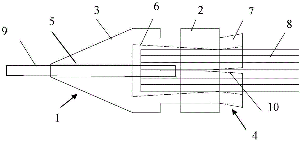
Figure 1 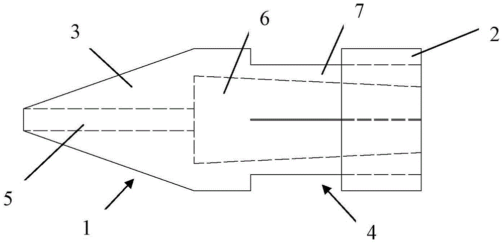
Figure 2 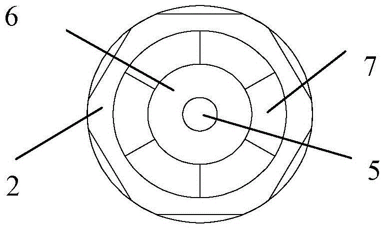
Figure 3
Abstract
Description
technical field
[0001] The invention belongs to the technical field of prestressed steel bar traction in bridge construction engineering, in particular to an ultra-long prestressed steel bar traction locking device. Background technique
[0002] Bridges are usually located at the throat of the urban traffic network, holding the lifeblood of urban traffic. Long-span bridges are bridges with relatively large spans in bridge construction, featuring large spans and long construction periods. With the maturity of bridge construction technology, the proportion of long-span bridges is increasing. In the construction of long-span bridges, during the construction of the bridge deck, it is necessary to apply prestress to the tendons penetrating into the main structure of the bridge, then fix the tendons and perform grouting, and relax the prestressed tendons after the concrete solidifies to make the main structure of the bridge Obtain a prestress value after construction is complete...
Examples
Embodiment Construction
[0014] The ultra-long prestressed steel bar traction locking device provided by the present invention will be described in detail below in conjunction with the accompanying drawings and specific embodiments.
[0015] Such as figure 1 — Figure 5 As shown, the ultra-long prestressed steel bar traction locking device provided by the present invention includes a restraint device 1 and a nut 2; wherein the restraint device 1 is integrally formed by a cone part 3 and a tail part 4, the cone part 3 is a frustum-shaped structure, and the front part A steel bar through hole 5 is formed at the axial center of the cone tip, and a steel bar setting hole 6 that communicates with the above steel bar through hole 5 and has a diameter greater than the steel bar through hole 5 is formed at the rear axial center; One end is connected to the edge of the tendon setting hole 6 on the rear end surface of the cone part 3 and is formed by a circular arc-shaped piece 7 with multiple gaps, and thread...