
Internal twisted tape testing system
A testing system, a technology of spiral ties, applied in the direction of testing wear resistance, measuring devices, instruments, etc., can solve the problem of inability to effectively verify the reliability of spiral ties, stay in the theoretical stage, and the operation of spiral ties cannot form real test conclusions, etc. problem, to achieve the effect of easy promotion, convenient operation and simple structure
Patent Information
- Authority / Receiving Office
- CN · China
- Patent Type
- Applications(China)
- Current Assignee / Owner
- Publication Date
- 2016-06-01
- Estimated Expiration
- Not applicable · inactive patent
Smart Images
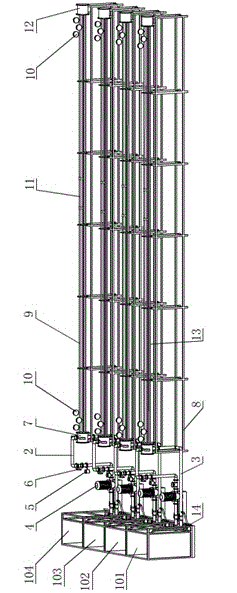
Figure 1 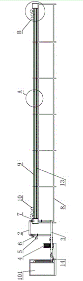
Figure 2 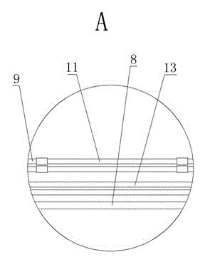
Figure 3
Abstract
Description
technical field
[0001] The invention relates to a test platform, in particular to a spiral bond test system. Background technique
[0002] Spiral ties, also known as twisted iron, spoilers, spiral flat steel, etc., are installed in heat exchanger tubes and are mainly used to improve heat exchange efficiency. When the fluid enters the heat exchange tube, the spiral bond makes the fluid flow in the tube in a spiral state along the spiral bond (that is, the fluid enters a turbulent state), which increases the contact area between the fluid and the heat exchange tube wall, and the spiral bond itself Driven by the flow energy of cooling water at a certain flow rate, automatic rotation and vibration will also occur. The side edge of the spiral bond can strongly disturb the boundary stagnant layer close to the tube wall. In convective heat transfer, the boundary layer with the largest thermal resistance The heat is effectively enhanced, thus greatly improving the heat transfer coe...
Examples
Embodiment Construction
[0032] The technical solution of the present invention is further described in conjunction with the accompanying drawings and embodiments.
[0033] Such as figure 1 As shown, the present invention includes four test platforms, and each test platform includes a water tank 1, a water inlet pipe 2, an outlet pipe 3, a circulating pump 4, a flow meter 5, a pressure valve 6, a diverter box 7, a support 8, a test tube 9, Pressure gauge 10, observation tube 11, reflux tank 12, reflux branch pipe 13, main conveying pipe 14, wherein:
[0034] The water tank 1 is used to contain the medium used in the simulated use environment, and the water tanks in the four test platforms are respectively a room temperature clean water tank 101, a room temperature sludge water tank 102, a high temperature oil tank 103 and a high temperature clean water tank 104;
[0035] One end of the water inlet pipe 2 is connected to the water tank 1, and the other end is connected to the diversion tank 7, for tra...