
Anti-scouring packer
A packer and anti-scouring technology, which is applied in the direction of sealing/packing, wellbore/well components, earthwork drilling and production, etc., can solve problems such as poor anti-scouring ability, no anchoring device, and damage to the rubber tube, and achieve anti-scouring Strong flushing ability, long service life and easy operation
Patent Information
- Authority / Receiving Office
- CN · China
- Patent Type
- Patents(China)
- Current Assignee / Owner
- Publication Date
- 2017-12-19
Smart Images
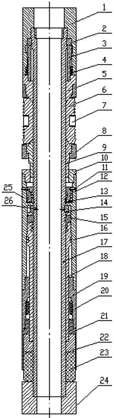
Figure 1
Abstract
Description
technical field
[0001] The invention belongs to downhole packers for oil development, in particular to an anti-scouring packer. Background technique
[0002] Publication number CN201250641Y, a Chinese patent authorized on September 3, 2009, discloses a "horizontal downhole flushing packer" whose structure is a leather bowl structure. The packer with this structure has played a role in oil exploitation, but it also has the following shortcomings or deficiencies: ①Because the cup seal is not heat-resistant, it is not suitable for thermal recovery of horizontal wells; ②There is no anchoring device, during the production process The movement of the sand control string is easy to occur; ③ During the running of the horizontal well sand control string, for the quicksand oil layer, sand washing cannot completely wash away the remaining sand in the horizontal section, and the process of flushing and running must be adopted. It is relatively complex; ④ During the sand washing process...
Examples
Embodiment Construction
[0014] refer to figure 1 , an anti-scouring packer, including an unsealing joint 1, an unsealing ring 2, a connecting joint 3, a retaining ring 4, an upper cone 5, a slip 6, a spring leaf 7, a slip cover 8, and a lower cone 9 , upper pressure cap 10, setting pin 11, piston 12, upper limit ring 13, lower limit ring 14, lock block 15, hydraulic sleeve 16, main shaft 17, pressure transmission inner sleeve 18, pressure transmission sleeve 19, lock ring 20, Rubber sleeve protective cover 21, sliding joint 22, rubber sleeve 23 and lower joint 24. A main shaft 17 is installed and connected between the inside of the unsealing joint 1 and the inside of the lower joint 24, and the outside of the main shaft 17 is sequentially installed and connected with an unsealing ring 2, a connecting joint 3, an upper cone 5, slips 6, slip covers 8, Lower cone 9, upper pressure cap 10, piston 12, hydraulic sleeve 16, pressure transmission inner sleeve 18, pressure transmission sleeve 19, rubber slee...