
A phase selection method for transmission line ground faults against the influence of distributed capacitive current and transition resistance
A transmission line and distributed capacitance technology, applied in fault location, fault detection according to conductor type, measurement of electricity, etc., can solve the problem of insufficient phase selection sensitivity of phase voltage sudden change, phase selection of three-phase short-circuit fault and high-resistance grounding short-circuit fault sensitivity Insufficient, phase current mutation amount is not enough phase selection sensitivity, etc., to achieve the effect of high phase selection sensitivity, correct and reliable fault phase information
Patent Information
- Authority / Receiving Office
- CN · China
- Patent Type
- Patents(China)
- Current Assignee / Owner
- Publication Date
- 2018-10-19
- Estimated Expiration
- Not applicable · inactive patent
Smart Images
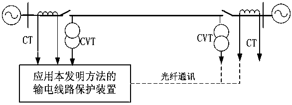
Figure 1
Abstract
Description
technical field
[0001] The invention relates to the technical field of relay protection for power systems, in particular to a phase selection method for transmission line grounding faults against the influence of distributed capacitive currents and transition resistances. Background technique
[0002] Phase selection methods for transmission line faults mainly include phase selection of phase current mutation, phase selection of phase voltage mutation and comprehensive phase selection of voltage and current mutation. On the weak power supply side, the phase selection sensitivity of phase current mutation is not high enough; on the strong power supply side, the phase selection sensitivity of phase voltage mutation is insufficient; although the comprehensive phase selection method of voltage and current mutation has relatively high The sensitivity of phase selection is good, but the sensitivity of three-phase short-circuit fault phase selection and high-resistance grounding sh...
Examples
Embodiment Construction
[0017] The technical solution of the present invention will be further described in detail according to the accompanying drawings.
[0018] figure 1 It is a schematic diagram of the line transmission system applying the present invention. figure 1 The middle CT is a current transformer, and the CVT is a voltage transformer. The protection device measures the zero-sequence current at the protection installation at the m-end of the transmission line Zero sequence voltage Phase A negative sequence current A phase positive sequence current Phase A negative sequence voltage and A phase positive sequence voltage Measure the zero-sequence voltage at the n-terminal protection installation of the transmission line Phase A negative sequence current A phase positive sequence current
[0019] Protection device judgment and Whether it is established, and if it is established, the protection device judges that a single-phase ground short-circuit fault has occurred in ...