
Wavelength control device for adjustable optical module, and method thereof
A dimming module and wavelength control technology, which is applied to lasers, laser components, electrical components, etc., can solve the problems of complex coefficient adjustment, long adjustment time, and large area occupation, and achieve good dynamic stability, good controllability, and fast time effect
Patent Information
- Authority / Receiving Office
- CN · China
- Current Assignee / Owner
- Publication Date
- 2016-07-13
Smart Images
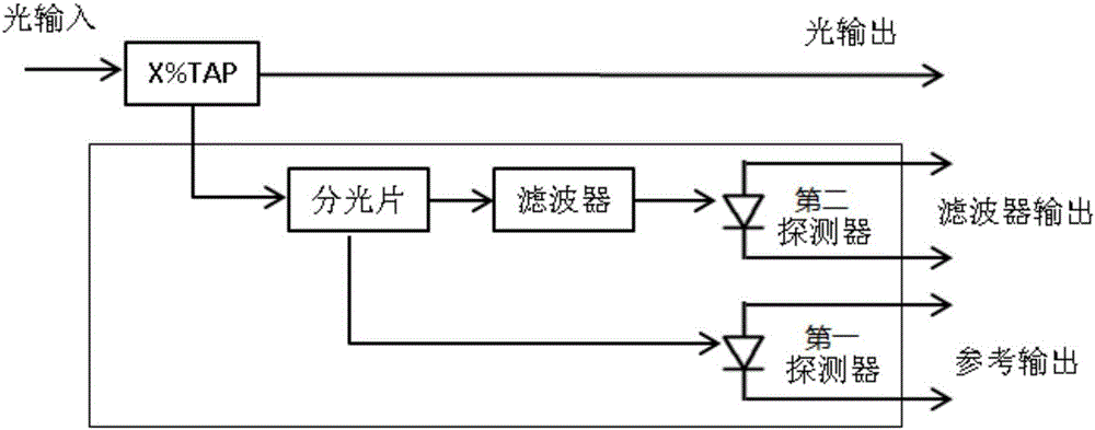
Figure 1 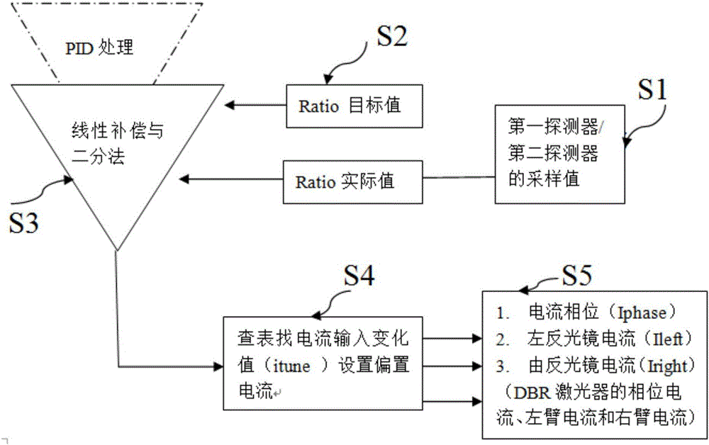
Figure 2 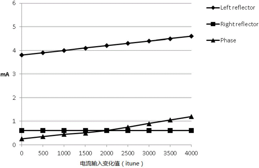
Figure 3
Abstract
Description
Technical field
[0001] The invention relates to a wavelength control device, in particular to a wavelength control device of a tunable optical module, and to a wavelength control method of the wavelength control device adopting the tunable optical module. Background technique
[0002] Due to changes in conditions such as temperature and self-aging, the output optical power and wavelength of the laser of the tunable optical module will change. In order to make the optical transmitter output stable optical power or wavelength information, corresponding negative feedback measures must be adopted to control the light source The luminous power, bias current or temperature of the device, such as: APC (automatic power control) and AFC (automatic frequency control and wavelength control), conventional automatic control is divided into hardware PID and software PID to achieve, such as a simple hardware APC The description of (automatic power control) is as follows: the light transmitted f...
Examples
Embodiment Construction
[0027] The preferred embodiments of the present invention will be further described in detail below in conjunction with the accompanying drawings.
[0028] Such as figure 1 As shown, this example provides a wavelength control device for a tunable optical module, which includes: a splitter, a filter, a first detector, and a second detector. The optical signal of the tunable optical module is divided into the first An optical path and a second optical path, the first optical path is connected to the input end of the first detector, and the output end of the first detector outputs a reference signal; the second optical path is connected to the second optical path through a filter Detector, output standard signal.
[0029] In this example, the second optical path is connected to the input end of the second detector through a filter, and the output end of the second detector is connected to the A / D sampling circuit to achieve a standard signal output after filtering; The ratio between ...