
Intelligent device USB eye pattern improvement method
A technology of smart devices and eye diagrams, applied in the field of communication, can solve problems such as difficult to change, unable to effectively improve USB eye diagrams, and difficult to reduce the length of traces, etc., to achieve the effect of improving USB eye diagrams, simplicity and practicability
Patent Information
- Authority / Receiving Office
- CN · China
- Current Assignee / Owner
- Publication Date
- 2016-07-27
- Estimated Expiration
- Not applicable · inactive patent
Smart Images
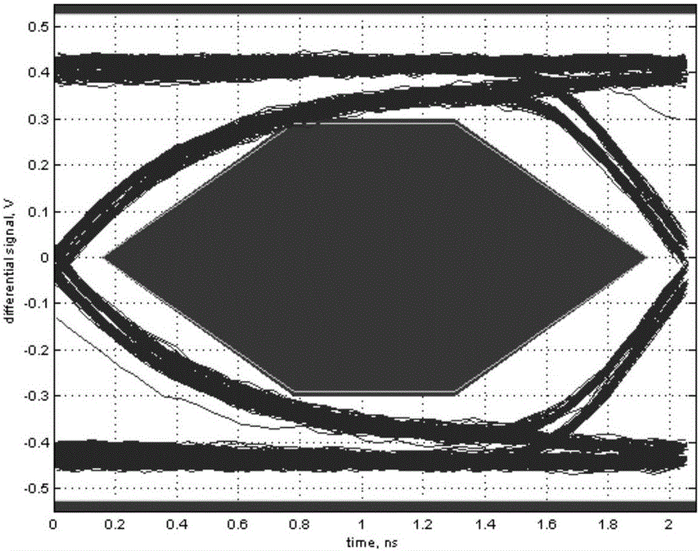
Figure 1 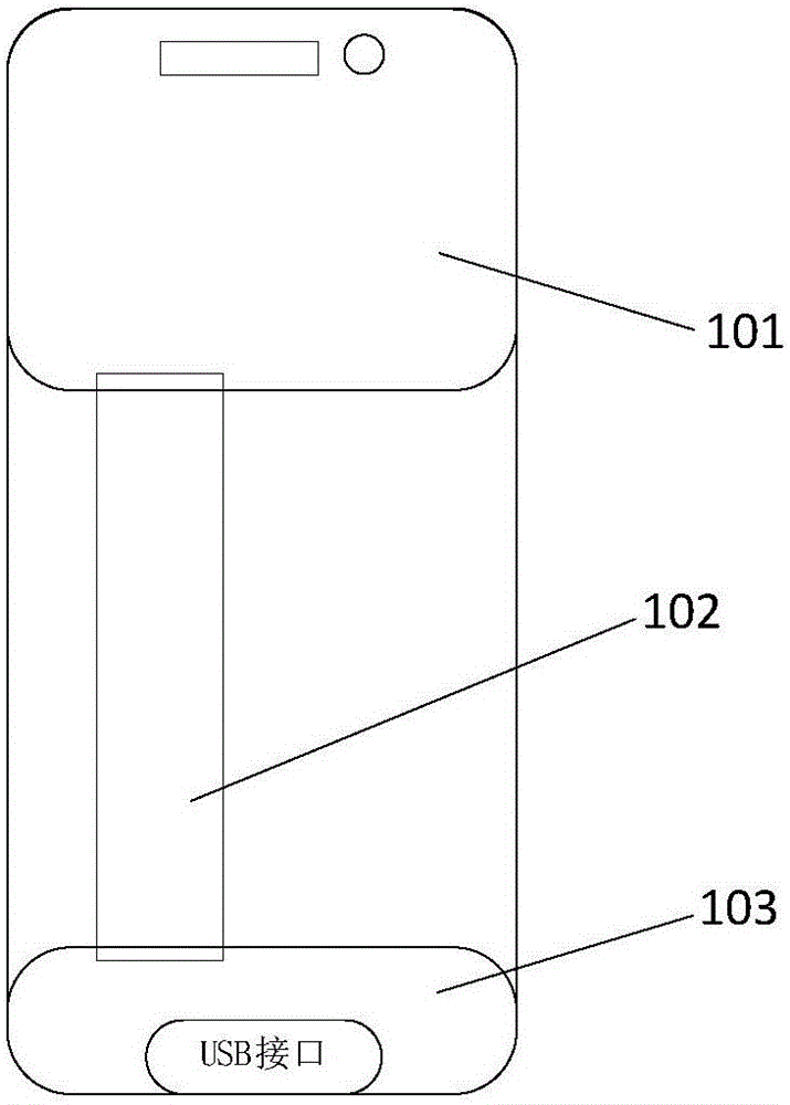
Figure 2 
Figure 3
Abstract
Description
technical field
[0001] The present disclosure relates to the technical field of communication, and in particular to a method for improving a USB eye diagram of a smart device. Background technique
[0002] At present, most smart devices are equipped with a USB (English: Universal Serial Bus, Chinese: Universal Serial Bus) interface to realize connection and communication between the smart device and external devices. Generally, data transmission can be performed between the processor of the smart device and the USB interface through two ribbon differential lines D+ and D-.
[0003] In the design stage and verification stage of smart devices, in order to ensure the stability of USB interface data transmission, it is necessary to perform an eye diagram test on the USB interface to detect whether the quality of the signal transmitted by the two ribbon differential lines meets the USB standard.
[0004] figure 1 It is a USB eye diagram shown according to an exemplary embodimen...
Examples
Embodiment Construction
[0028] Reference will now be made in detail to the exemplary embodiments, examples of which are illustrated in the accompanying drawings. When the following description refers to the accompanying drawings, the same numerals in different drawings refer to the same or similar elements unless otherwise indicated. The implementations described in the following exemplary examples do not represent all implementations consistent with the present disclosure. Rather, they are merely examples consistent with aspects of the disclosure as recited in the appended claims.
[0029] Usually, when designing smart devices, the AP (English: Application Processor, Chinese: Application Processor) is placed above the smart device, the USB interface is placed below the smart device, and the two ribbon differential lines D+ and D- are connected to the processing Between the processor and the USB interface, and together with the processor and the USB interface, it is arranged on the PCB board of the ...