
Closed electrical rotating machine
A rotary motor, sealed technology, applied in the direction of electrical components, electromechanical devices, electric components, etc., can solve problems such as copper loss, and achieve the effect of ensuring heat dissipation
Patent Information
- Authority / Receiving Office
- CN · China
- Patent Type
- Applications(China)
- Current Assignee / Owner
- Publication Date
- 2016-07-27
- Estimated Expiration
- Not applicable · inactive patent
Smart Images
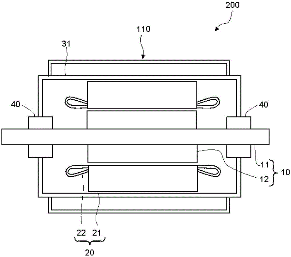
Figure 1 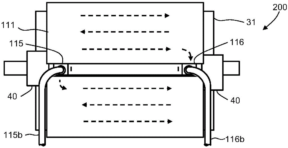
Figure 2 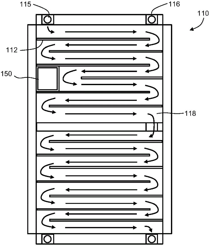
Figure 3
Abstract
Description
technical field
[0001] The present invention relates to a hermetic rotating electric machine. Background technique
[0002] A current corresponding to the output of the rotating electrical machine flows through the stator coils of the rotating electrical machine. Copper loss occurs due to Joule heat due to the flow of current. Insulators are provided between the conductors of the stator coil or between the conductors of the stator coil and structures such as the stator core and the support portion to prevent short circuits.
[0003] The material of the insulator is different for each insulation class corresponding to the temperature condition. Cooling of the stator is also important in order to ensure sufficient insulating effect of the insulation.
[0004] As a technique for externally cooling a stator of a hermetically sealed rotating electrical machine, an example is known in which cooling holes are provided in the plate thickness of the frame (Patent Document 1). In ...
Examples
Embodiment approach 1
[0027] figure 1 It is a front sectional view showing the structure of the sealed rotating electrical machine according to Embodiment 1. The sealed rotating electric machine 200 has a rotor 10 , a stator 20 , a frame 31 , bearings 40 , and an external cooling structure 110 .
[0028] The rotor 10 has a rotating shaft 11 rotatably supported at both ends, and a cylindrical rotor core 12 fixed to the radially outer side of the rotating shaft 11 . The stator 20 has a cylindrical stator core 21 and a stator coil 22. The stator core 21 is statically fixed on the radially outer side of the rotor core 12 and is opposite to the rotor core 12. The stator coil 22 is laid in a slot not shown in the figure. The slots are formed in the vicinity of the inner surface of the stator core 21 , are arranged parallel to each other at intervals in the circumferential direction, and extend in the axial direction.
[0029] The frame 31 has a cylindrical shape and extends in the axial direction, acco...
Embodiment approach 2
[0044] This embodiment is a modification of the first embodiment. In the second embodiment, the partition member forming the coolant flow path inside the closed space 118 is different from the first embodiment. Figure 4 is a side view of the sealed rotating electrical machine according to Embodiment 2, but as Figure 4As shown, the appearance of the second embodiment is the same as that of the first embodiment.
[0045] Figure 5 It is a circumferential development view of the external cooling structure of the sealed rotating electrical machine of Embodiment 2. The structure of the flow path of the external cooling structure 120 is the same as that of Embodiment 1, and the flow direction is formed in an axial direction and alternately reversed. A plurality of first short partitions 122 and a plurality of second short partitions 123 are included as partition members. That is, a plurality of first short partitions 122 and a plurality of second short partitions 123 are arran...
Embodiment approach 3
[0051] This embodiment is a modification of the first embodiment. Figure 6 It is a side view of the sealed rotating electric machine according to Embodiment 3. In Embodiment 3, the cooler cover plate 131 is provided on the entire periphery except for the injection portion 115 and the discharge portion 116 .
[0052] Figure 7 It is a circumferential development view of the external cooling structure of the sealed rotating electrical machine of Embodiment 3. In this embodiment, a spiral partition plate 133 is provided as a partition member of the external cooling structure 130 . The spiral partition plate 133 is perpendicular to the axial direction and inclined along the circumferential direction, that is, installed in a spiral shape. In this embodiment, the flow path of the cooling medium is a flow path in only one direction. That is, the cooling medium flowing into the sealed space 118 from the injection part 115 advances in the circumferential direction in the sealed sp...