
Low-voltage integrated distribution box
A distribution box, low-voltage technology, applied in electrical components, substation/switch layout details, substation/switchgear cooling/ventilation, etc. The problem of poor rainproof performance, etc., can save the cost of centralized copying and maintenance, save the cost of centralized copying and maintenance, and have strong installation and mobile performance.
Patent Information
- Authority / Receiving Office
- CN · China
- Patent Type
- Applications(China)
- Current Assignee / Owner
- Publication Date
- 2016-09-07
- Estimated Expiration
- Not applicable · inactive patent
Smart Images
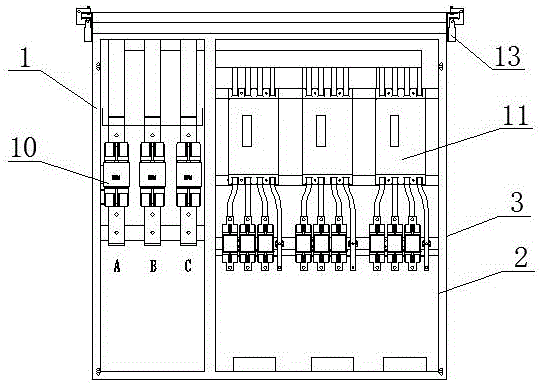
Figure 1 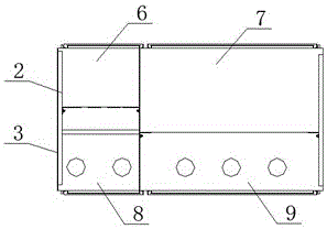
Figure 2 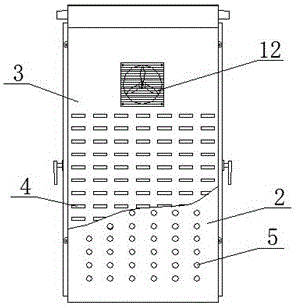
Figure 3
Abstract
Description
technical field
[0001] The invention relates to a low-voltage integrated distribution box, which belongs to the technical field of electric equipment. Background technique
[0002] The existing integrated distribution box has a small space inside the shell, and the installation of the components is relatively compact, which is easy to cause heat; the size and installation method of each box are different, the cable connection is complicated and tortuous, and the installation is inconvenient; there is no installation of capacitance compensation inside Space; the air circulation with the outside world is not smooth, which is likely to cause tripping; there is no remote detection and remote control function; the seat and hoisting brackets are not universal, and it is inconvenient to move the distribution box; the rainproof performance of the louvered windows is not good, and it is easy to It will cause the switch to be damp and the cabinet to accumulate water, which poses a gre...
Examples
Embodiment Construction
[0024] The present invention will be described in further detail below in conjunction with the accompanying drawings.
[0025] refer to figure 1 .
[0026] A low-voltage integrated distribution box, including a box shell 1, the box shell 1 is divided into four working rooms, which are respectively a metering room 6, a capacitance compensation room 7, an incoming line room 8 and an outgoing line room 9. A residual current operated circuit breaker 10 is provided inside the metering chamber 6, a fuse 3 is provided inside the capacitance compensation chamber 7, an inner panel 2 and an outer panel 3 are provided on the left and right sides of the housing 1, and the inner panel 2 is provided with A first ventilation hole 5 is provided, and a second ventilation hole 4 is provided on the outer plate 3 .
[0027] The diameter of the second ventilation hole 4 is larger than that of the first ventilation hole 5 , and the first ventilation hole 5 and the second ventilation hole 4 are st...