
Cylindrical surface triangular central symmetry arrayed electrostatic spinning spray head and spinning method
A centrosymmetric, electrospinning technology, applied in textiles and papermaking, filament/thread forming, fiber processing, etc., can solve problems such as uneven spinning, large difference in electric field of nozzles, interference, etc. The effect of small intensity differences
Patent Information
- Authority / Receiving Office
- CN · China
- Current Assignee / Owner
- Publication Date
- 2016-11-16
- Estimated Expiration
- Not applicable · inactive patent
Smart Images
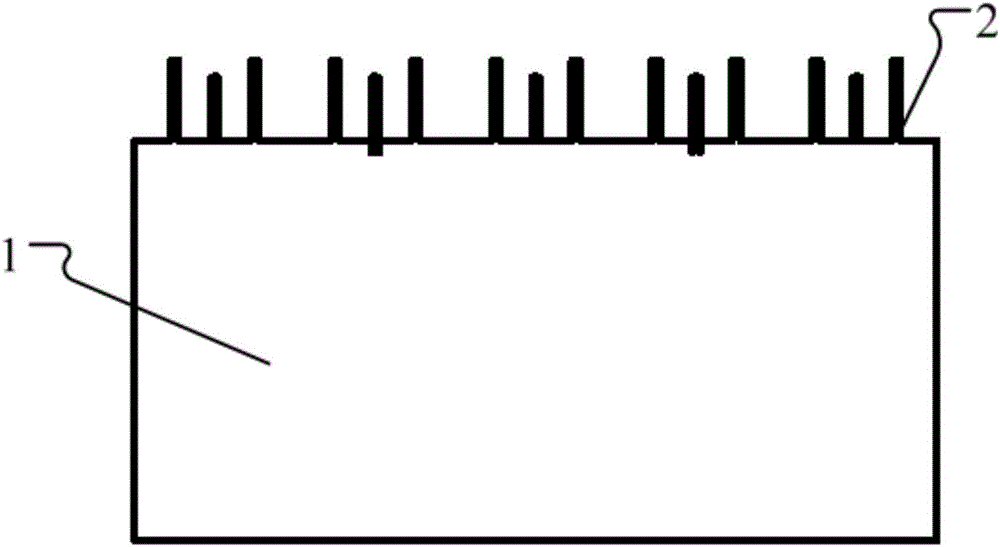
Figure 1 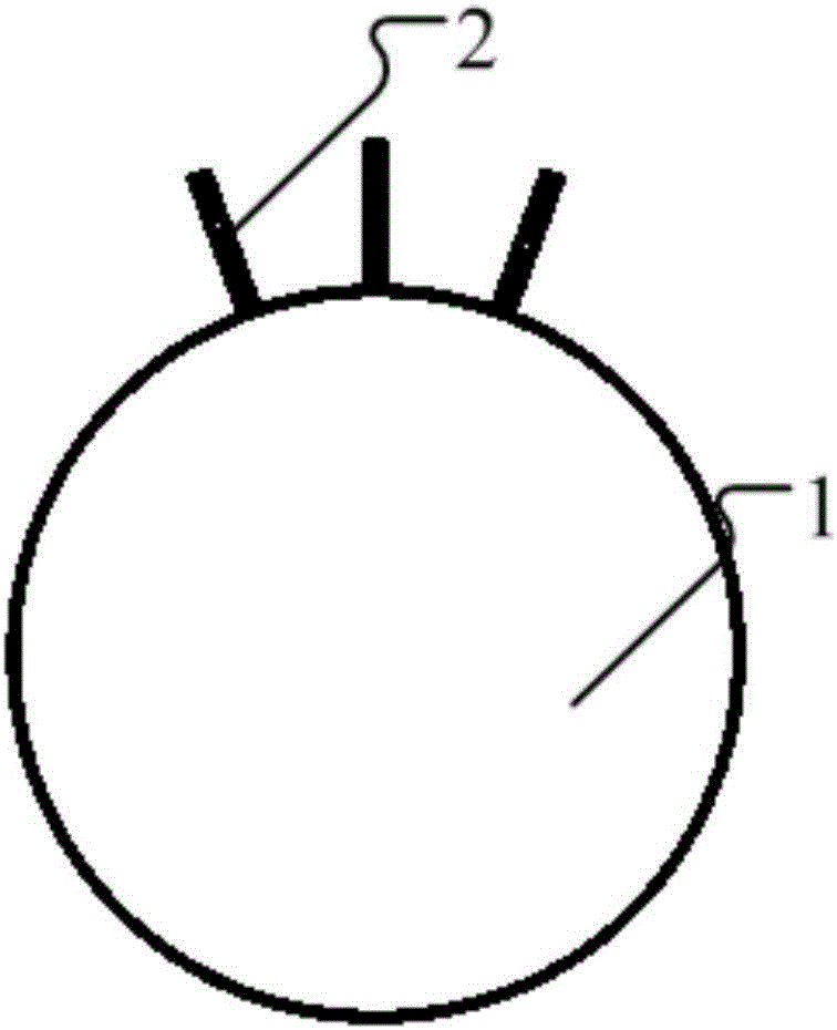
Figure 2 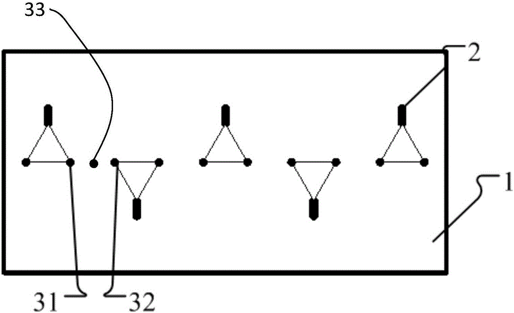
Figure 3
Abstract
Description
technical field
[0001] The invention relates to the field of electrospinning, in particular to an electrospinning nozzle and a spinning method with a cylindrical triangular centrosymmetric array. Background technique
[0002] The invention patent with the application number 200910031948.2 discloses an array multi-nozzle electrospinning equipment, which uses multiple nozzles arranged in a linear rectangular array on the plane for spinning, which can realize mass production of electrospun fiber membrane materials.
[0003] However, after a long period of use, technicians found that when the nozzles are arranged in an array on a plane, the electric fields at the tips of the nozzles will affect and interfere with each other, resulting in large differences in the electric fields between different nozzles, resulting in uneven spinning. Contents of the invention
[0004] In order to solve the above problems, the object of the present invention is to provide an electrospinning noz...
Examples
Embodiment Construction
[0027] Such as Figure 1 to Figure 3 The electrospinning nozzle of the cylindrical triangular centrosymmetric array shown includes a body 1, the body 1 has a cylindrical surface at the top and is provided with at least three sets of output structures, and the output structures are used to collect and spray spinning solution .
[0028] Each set of output structure is composed of three connecting holes on the cylindrical surface and needle nozzles 2 respectively connected to the connecting holes. The connecting holes in the drawings coincide with the needle nozzles 2, so the connecting holes are in figure 1 with figure 2 Not marked in . The connecting lines of these three connecting holes form a triangular trajectory, that is, the three connecting holes are on the endpoints of a triangle, and the connecting line segments of two connecting holes are parallel to the axis of the cylindrical surface. In other words, by this One of the sides of the triangle formed by the three co...