
Mechanical changer for changing end effectors
A mechanical and damper technology, which is applied in the field of mechanical replacement devices, can solve problems such as unsatisfactory bonding strength, hazards to replacement device staff, and inconvenient operation
Patent Information
- Authority / Receiving Office
- CN · China
- Patent Type
- Patents(China)
- Current Assignee / Owner
- Publication Date
- 2018-11-06
Smart Images
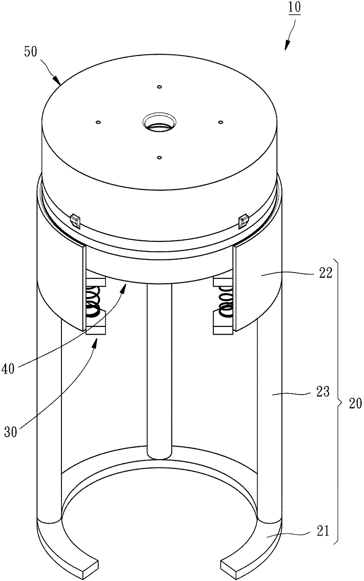
Figure 1 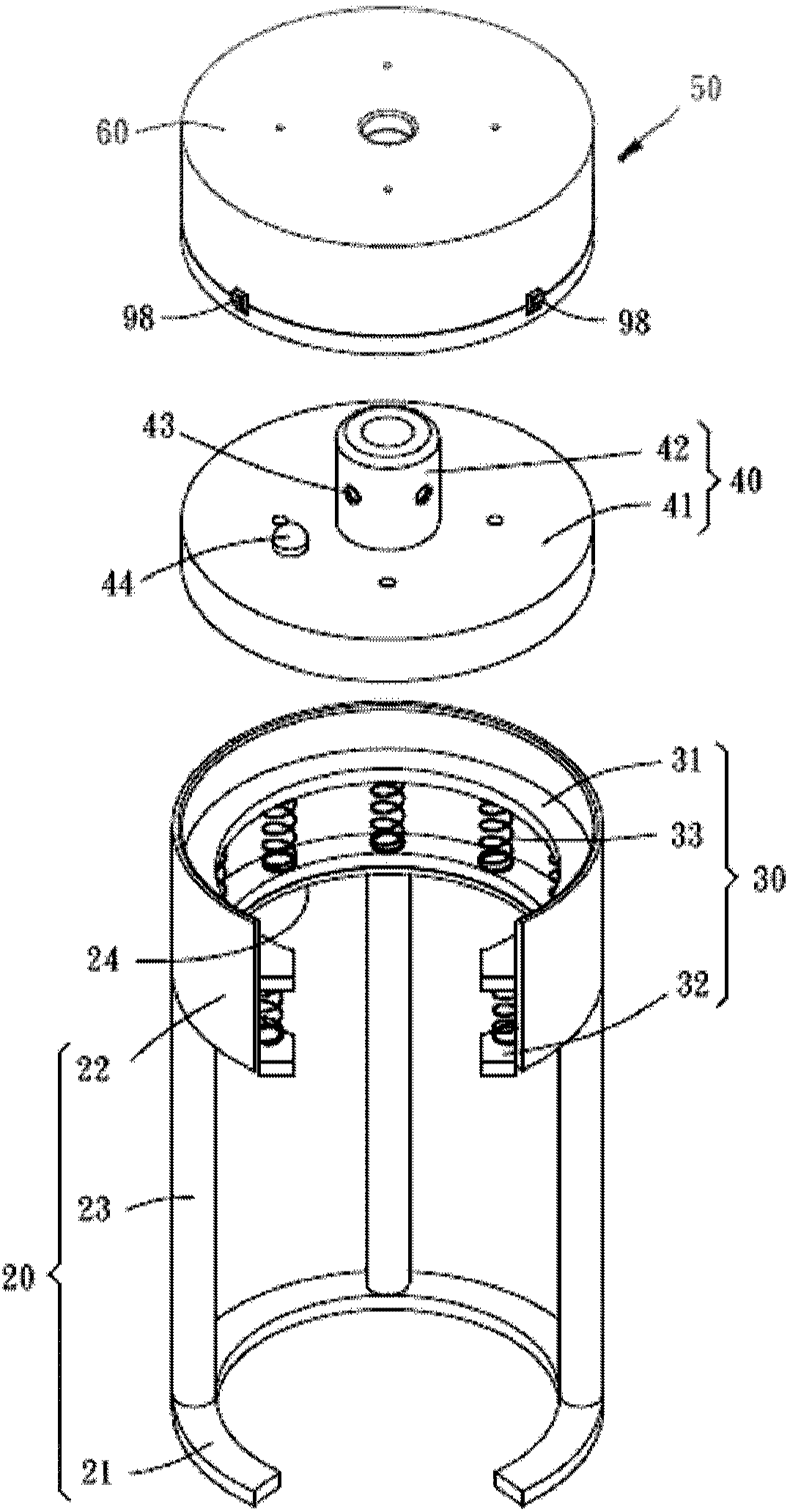
Figure 2 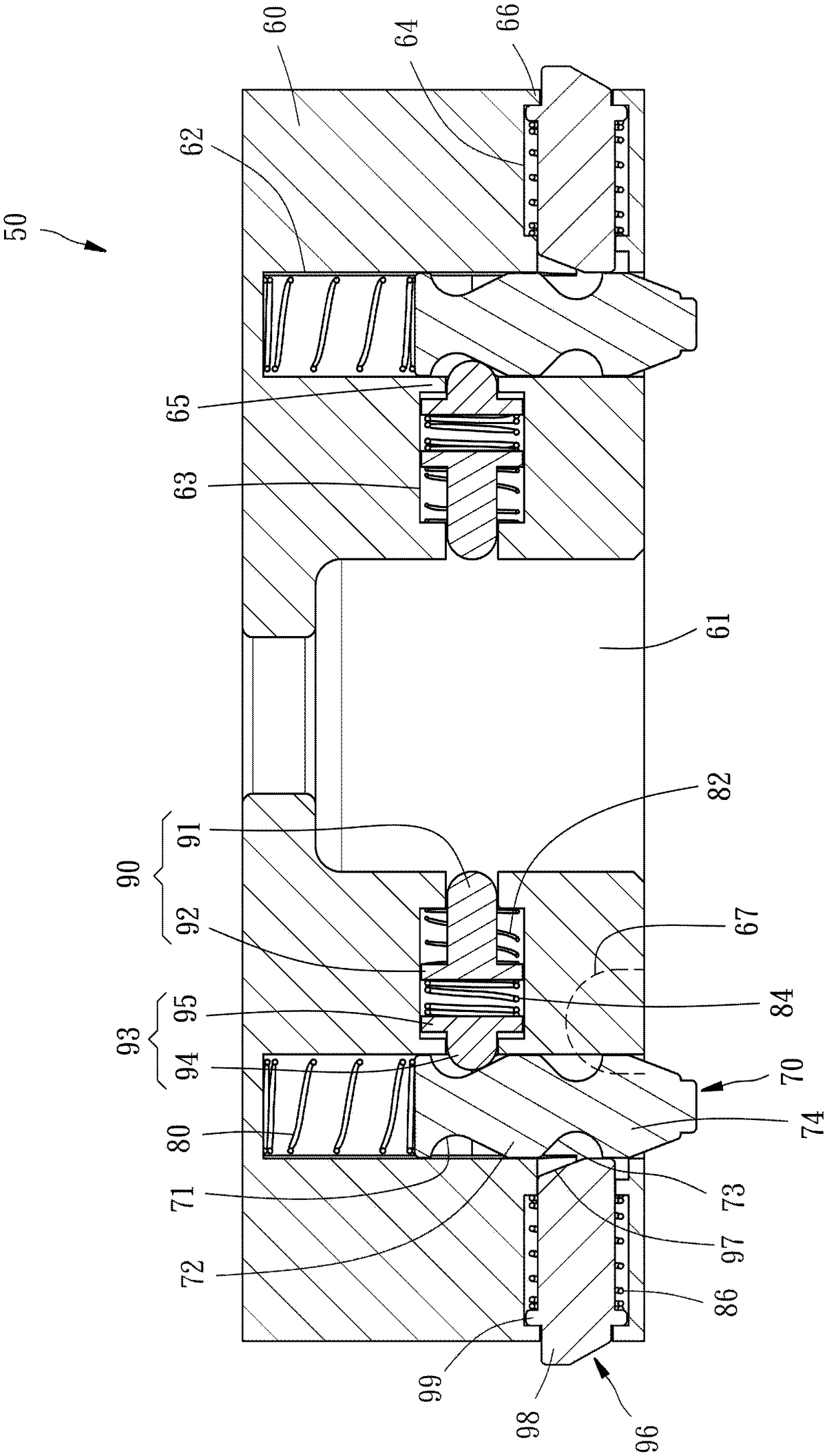
Figure 3
Abstract
Description
technical field
[0001] The invention relates to a device for replacing an end effector used with a mechanical arm, in particular to a mechanical replacement device. Background technique
[0002] Robotic arms have been widely used in the manufacturing and processing industry at present. On the one hand, it can reduce the reduction of product yield caused by manual execution of highly repetitive workflows. On the other hand, it can replace manual work in harsh environmental conditions. , so that the health of the staff can be avoided, and at the same time, good processing accuracy can be maintained. However, during the manufacturing process, the robot arm must be equipped with a replacement device to replace end effectors of different specifications (such as grippers, suction cups or drills), so as to process workpieces of different specifications.
[0003] As far as the prior art of the replacement device is concerned, at first such as U.S. Patent No. 6,073,512 is to manuall...
Examples
Embodiment Construction
[0045] see figure 1 and figure 2 , the mechanical replacement device 10 of the first embodiment of the present invention includes a base 20 , a damper 30 , a first connection unit 40 , and a second connection unit 50 .
[0046] The base 20 has a bottom wall 21, a ring wall 22 above the bottom wall 21, and three support rods 23 connected between the bottom wall 21 and the ring wall 22, wherein the inner ring surface of the ring wall 22 has an inner flange24.
[0047] The damper 30 can choose to use a viscoelastic damper, a hydraulic damper or a vibration damper. In this embodiment, a viscoelastic damper 30 (Viscoelastic damper) is the best implementation, but not limited thereto. The damper 30 has an upper support plate 31 , a lower support plate 32 , and a plurality of viscoelastic damping elements 33 connected between the upper and lower support plates 31 , 32 . When assembled, the damper 30 is placed on the inner flange 24 of the ring wall 22 of the base 20 through the l...