
Torque adjustable overload prevention shaft transmission mechanism
A shaft transmission, anti-overload technology, applied in the field of mechanical transmission, can solve the problem that the anti-overload function cannot be reused many times, and achieve the effect of easy automatic disengagement and recovery, increased surface hardness, and simple setting.
Patent Information
- Authority / Receiving Office
- CN · China
- Current Assignee / Owner
- Publication Date
- 2017-03-15
- Estimated Expiration
- Not applicable · inactive patent
Smart Images
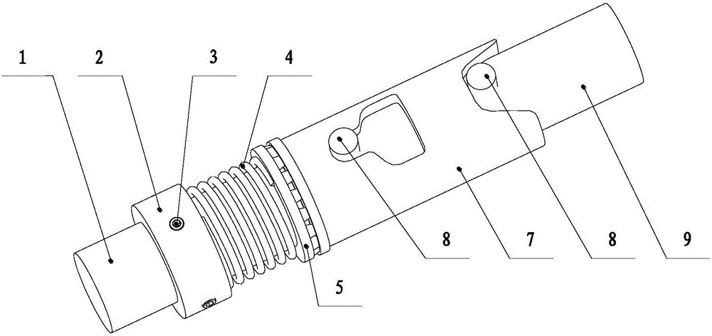
Figure 1 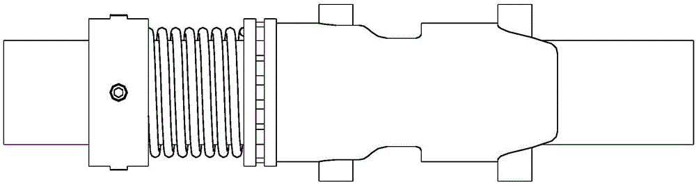
Figure 2 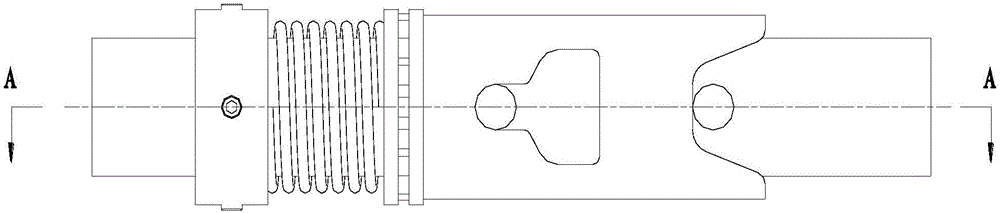
Figure 3
Abstract
Description
technical field
[0001] The invention belongs to the technical field of mechanical transmission, and in particular relates to a mechanism for shaft transmission with overload prevention and simple torque adjustment. Background technique
[0002] The two shafts (driving shaft and driven shaft) in different mechanisms in the mechanical device make them rotate together to transmit the speed and torque. The device used is generally a coupling or a coupling sleeve. In actual use, the driving shaft is generally It is the drive output shaft, such as the output shaft of the reducer or the motor shaft, and the driven shaft is the input shaft of the driven equipment. In shaft transmission applications, the phenomenon of overload of the driven equipment often occurs, that is, the load of the driven equipment suddenly increases. At this time, forced driving is likely to cause failure of the driving equipment or the driven equipment and cause accidents, such as motor burnout, drive shaft ...
Examples
Embodiment Construction
[0030] The present invention will be described in detail below with reference to the accompanying drawings and examples.
[0031] The invention provides an anti-overload shaft transmission mechanism with adjustable torque, such as figure 1 As shown, the shaft transmission mechanism includes a driving shaft 1, a shaft sleeve 2, a tightening screw 3, a spring 4, a bearing 5, a driving shaft pin 6, a sliding sleeve 7, a driven shaft pin 8 and a driven shaft 9, and the driving shaft 1. The surface of shaft sleeve 2, sliding sleeve 7 and driven shaft 9 is quenched to increase surface hardness.
[0032] Such as Figure 6 As shown, the sliding sleeve 7 is a cylindrical structure with both ends open, and one end is provided with two grooves running through the end. The central axis of the two grooves is located at the end face of this end of the sliding sleeve 7; the sliding sleeve 7 is provided with a convex-shaped through hole that runs through the outer peripheral surface, and th...