
Heat exchanger
A technology for heat exchangers and radiators, applied in heat exchange equipment, indirect heat exchangers, heat exchanger types, etc., to solve problems such as large bending stiffness, excessive use of materials, and material waste
Patent Information
- Authority / Receiving Office
- CN · China
- Patent Type
- Applications(China)
- Current Assignee / Owner
- Publication Date
- 2017-05-17
- Estimated Expiration
- Not applicable · inactive patent
Smart Images
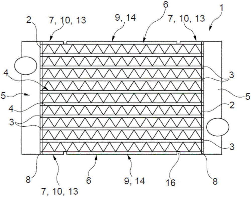
Figure 1 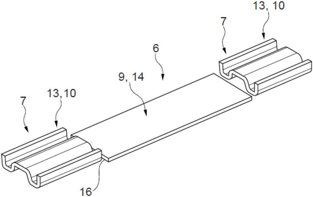
Figure 2 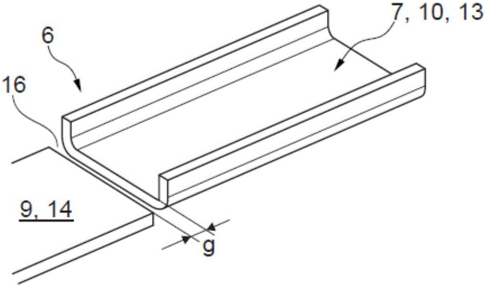
Figure 3
Abstract
Description
technical field
[0001] The invention relates to a heat exchanger, in particular an intercooler or a coolant radiator, according to the preamble of claim 1 . The invention further relates to side pieces for such heat exchangers. Background technique
[0002] A heat exchanger typically consists of a large number of tubes, especially flat tubes with or without turbulators, two floors and typically two side pieces on which plenums are mounted to complete the collector. The side parts used for this are usually stamped or embossed and typically consist of one piece. Furthermore, in order to reduce the induced thermal stresses, these side pieces are decorated with local expansion sections or they are divided into two mechanical parts in a manufacturing step after bonding.
[0003] For example, a heat exchanger in which each side piece is equipped with expansion beads is known from DE19753408A1.
[0004] A species-dependent heat exchanger is known from EP0748995B1, which has two ...
Examples
Embodiment Construction
[0021] according to figure 1 A heat exchanger 1 according to the invention, which can be realized, for example, as an intercooler, comprises two floor plates 2 each having a channel 3 , for example for receiving the longitudinal end regions of fluid-conducting tubes 4 , flat tubes. The floor 2 is connected to a plenum 5 to form a collector, eg for coolant. The respective longitudinal end regions 7 of the two side parts 6 are accommodated at least partially in a channel 8 at the end of the associated floor 2 , wherein the channel 8 is likewise formed at the end by the channel 3 provided for the pipe 4 . The side pieces 6 can pass partially or all the way through the channel 8 , but do not have to. Alternatively, of course, they can also be joined to the floor 2 in some other way, for example by soldering, welding or the like.
[0022] Now, in order to be able to produce a side part 6 which not only meets the more demanding bending stiffness requirements present in the longitu...