
Snowflake machine roller
A technology of snowflake machine and roller, which is applied in ice making, lighting and heating equipment, leisure ice making, etc. It can solve unresolved technical problems and other problems, and achieve the effect of reasonable design, improved condensation effect and consistent hardness
Patent Information
- Authority / Receiving Office
- CN · China
- Patent Type
- Applications(China)
- Current Assignee / Owner
- Publication Date
- 2017-06-13
Smart Images
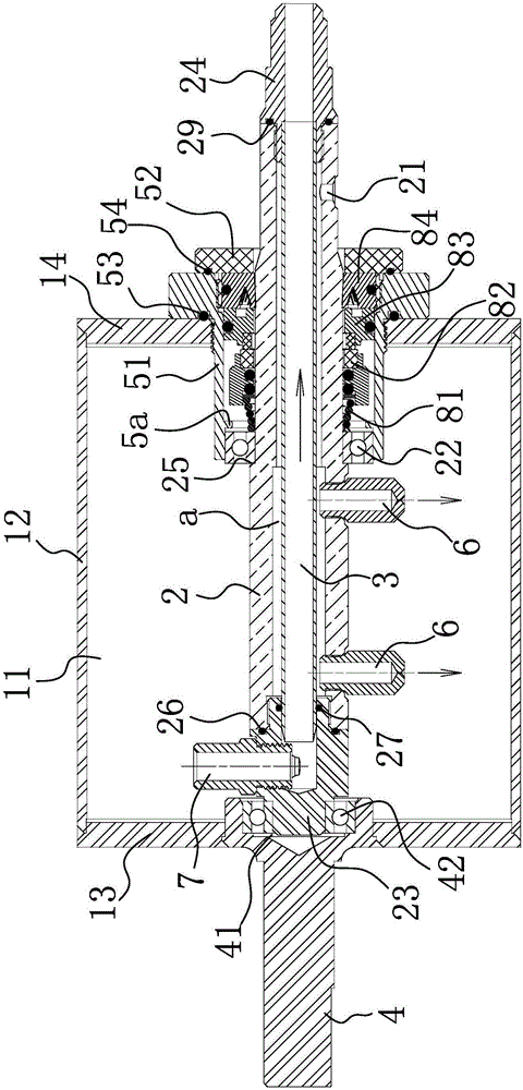
Figure 1 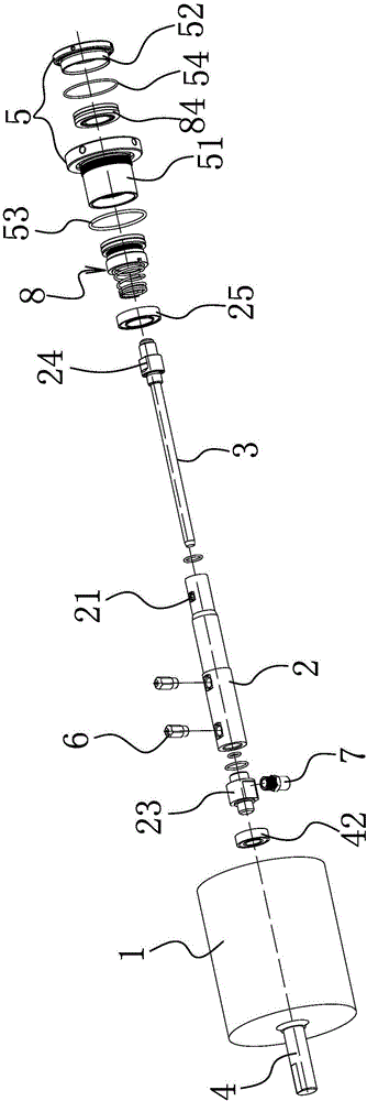
Figure 2 
Figure 3
Abstract
Description
technical field
[0001] The invention belongs to the technical field of snowflake machines, and in particular relates to a snowflake machine roller. Background technique
[0002] The sealing method of the snowflake machine drum in the existing market adopts O-ring for axial sealing. When the drum is stationary, the O-ring can play a good sealing effect, but when the drum is running and the compressor is running, there is a gap between the drum and the sealing ring. Relative movement, and there is high pressure inside the drum, the O-ring cannot achieve a good sealing effect, resulting in leakage of Freon, resulting in a decline in cooling effect or failure to cool after a long time.
[0003] For example, Chinese patent literature discloses a flavored snowflake machine [Application No.: 201420420841.3], which includes a snow-making device, which includes a snow-making drum evaporator, a liquid storage box, a cutter, a water inlet, a water inlet valve, a transmission The motor...
Examples
Embodiment Construction
[0032] The following are specific embodiments of the invention and in conjunction with the accompanying drawings, the technical solutions of the present invention are further described, but the present invention is not limited to these embodiments.
[0033] Such as Figure 1-2 As shown, the roller of this snowflake machine includes a roller body 1 with a cavity 11 inside, and the roller body 1 includes a roller ring 12, a left end cover 13 is provided at one end of the roller ring, and a right end cover 14 is provided at the other end of the roller ring. The axial center of the left end cover 13 is provided with a left mounting hole, and the axial center of the right end cover 14 is provided with a right mounting hole. The axis line of the left mounting hole coincides with the axis line of the right mounting hole. 13 joints are welded and connected, and the joints of the roller ring 12 and the right end cover 14 are welded and connected, that is, leakage at the joints is avoid...